Tekla 2024 top features
1min read+PDF+video
Here is the list of our favorite features and updates in Tekla Structures 2024.
ARVE error: Mode: lightbox not available (ARVE Pro not active?), switching to normal mode
CONTENTS
1. The list of “Top 6”
- Adding Bolts
- More Colors in Drawings
- Interactive Rotation
- Shop Drawings / Cloning
- BCF Topics
- IFC Export Property Sets
2. Trimble official links
- Tekla Structures official link HERE
AUTHOR
FIND THIS USEFUL? SHARE IT!
[Sassy_Social_Share_Pro]
YOU MIGHT ALSO LIKE


Tekla Structures is one of the most capable and advanced BIM software in its field, but the downside to this is that it takes a little longer to learn as it has more tools, settings, possibilities, and opportunities for customization.
But don’t worry – you’re not alone!
In this article, I will provide you an overview of different methods with pros and cons on how you can start learning Tekla Structures right away. No jargon, no confusing tech talk—just a straightforward roadmap with all the links to help you get started.
Watch and listen it all in video format:
ARVE error: Mode: lightbox not available (ARVE Pro not active?), switching to normal mode
or keep reading the article.
CONTENTS
Learning Tekla is like buying a car
Learning Tekla is akin to purchasing a car, or virtually anything else. There are three options from which to choose:
- The Best of the Best: These are top-tier options that provide the quickest and most likely path to achieving your desired results. However, they come at a higher price point. While this choice may exceed the budget of some individuals, for companies, it’s a highly recommended consideration. When compared to the alternatives, the cost is relatively minimal. The return on investment derives from saved time and the increased high-level efficiency it yields.
- Average: The second option is to opt for an averagely priced course, or even more economical ones if you’re on a tight budget. These courses are less expensive but may come with compromises in quality. Hidden fees can be an issue, akin to an older, cheaper car needing frequent repairs. As the cost of the training course decreases, so does its quality. You’ll gain a foundational understanding, but deeper insights into the software and its full potential may be lacking. Learning from your mistakes and gaining insight while working can be a lengthy and costly process.
- Free or DIY 🙂: Some individuals may face budget constraints and limited options. In such cases, making the most of what’s available is essential. While reaching the top is possible, it may require more effort and time. This article also provides information on various free resources to get started with the right tools, allowing for self-development without the financial burden.
I personally recommend selecting the option that aligns with your budget while avoiding excessive comfort, as growth often occurs beyond one’s comfort zone.
Different Ways To Learn Tekla Structures For Beginners:
01 Learning Tekla Structures Through Live Classroom Training
One effective method to learn Tekla Structures is via live classroom training. After downloading Tekla Structures, Trimble recommends contacting your local Trimble office for live classroom training. You can find these contacts also from HERE.
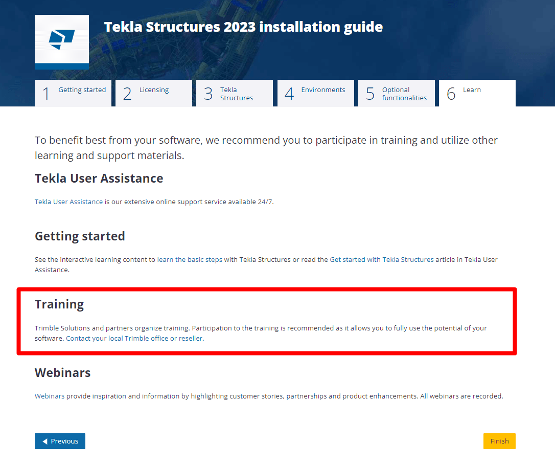
While this option may be more expensive, it’s advisable if your budget allows. The following paragraph will explore the difference between live and online training to help you determine the best approach.
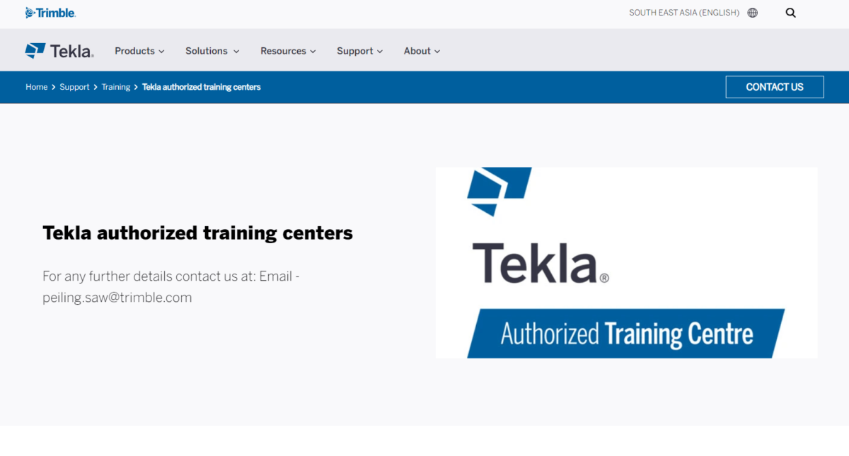
In addition to Trimble’s own offices and resellers, there are Trimble partnering companies and schools that offer Tekla training. Check for available options in your area.
Difference Between Live Training and Online Training
Before choosing between live and online training, it’s essential to understand their respective advantages and drawbacks.
Live Training
Live training is advantageous because trainers can tailor the curriculum to your company’s specific needs based on the types of structures you work with. Additionally, it allows for immediate interaction and problem-solving between instructors and students. However, live training requires physical attendance at specific times and locations, and its availability may be limited.
Online Training
Online courses are more flexible in terms of scheduling and location. They permit self-paced learning and offer affordability. However, online courses may lack customization to your specific needs and may not provide the same level of interaction as live training.
What to Consider When Enrolling in a Tekla Structures Course
Whether you’re pursuing your studies through online classes or live classrooms, there are several key factors to keep in mind before committing to a Tekla Structures course. It’s essential to have a comprehensive understanding of the course offering. For example:
- Course Content: You should have access to detailed information regarding the modules and lessons that will be covered. This information will give you a clear picture of what you’ll be learning.
- Course Duration: The length of the course is a significant indicator of the depth the instructor plans to delve into the topic. It will help you determine if the course provides a general overview or if it includes in-depth explanations, practical examples, and valuable tips and tricks.
- Teaching Methodology: Understand how the course content will be taught, how instructors will address questions, and how they will guide you through your initial project. You may want to know if the course includes theory tests or practical exercises for evaluation.
- Post-Course Opportunities: It’s crucial to know what students can expect to achieve after completing the course. Will you acquire practical skills that can be applied in the real world?
- Instructor Credentials: Investigate the background and credentials of the instructor. They should possess both solid practical experience with Tekla and a proven track record in teaching.
Apart from the instructor’s qualifications, it’s beneficial to assess the reputation and history of the educational institution offering the course. Look for signs of trustworthiness and consider their specialization.
While the course provider’s information is important, don’t solely rely on their promotional materials. Seek feedback from other students, as their perspectives tend to be more objective. You can do a quick online search on platforms like Google and LinkedIn to verify the authenticity of reviews. Be cautious of reviews without names or pictures, as they may be less reliable.
Price transparency is also essential. If the course provider doesn’t publicly disclose the cost, it’s a potential red flag. Transparency is key when making an informed decision about your investment in the course.
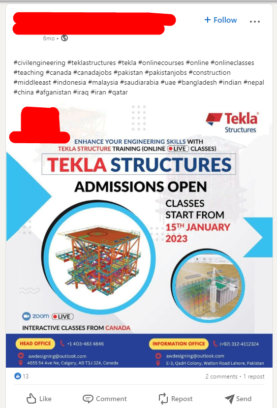
As the saying goes, “Don’t buy a pig in a poke.” Ensure you have access to all the necessary information before making a commitment. Missing or hidden details often indicate a lack of quality, something you’ll want to avoid. For instance, be cautious of social media posts that lack links to additional information.
Remember that a well-informed decision is more likely to lead to a successful educational experience.
02 Learning Tekla Structures Through “Top Level” Online Courses
Finding comprehensive online courses for Tekla Structures can be challenging. However, options like TSAcademy offer high-quality content in English.
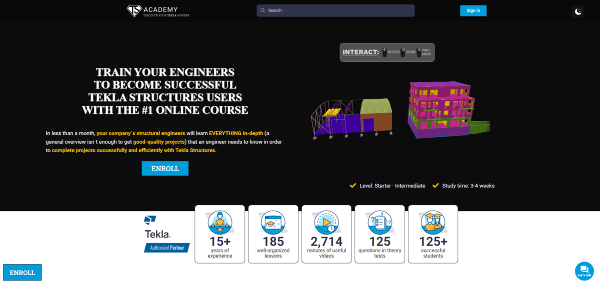
If you speak Spanish, Construsoft campus is another credible online training option.

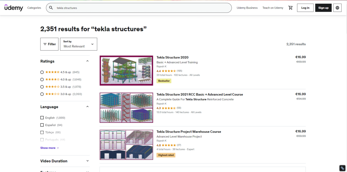
03 Learning Tekla Structures Through “Mid or Low Level” Online Courses
Udemy and Coursera offer cost-effective Tekla courses. While these platforms may provide a basic understanding, you might need to explore multiple courses to gain a broader knowledge of the software.
Learning Tekla Structures Through Free Materials
While “free” is enticing, these resources often cater to beginners. They serve as a starting point, providing introductory knowledge. The journey to deeper expertise may require additional self-learning through various sources.
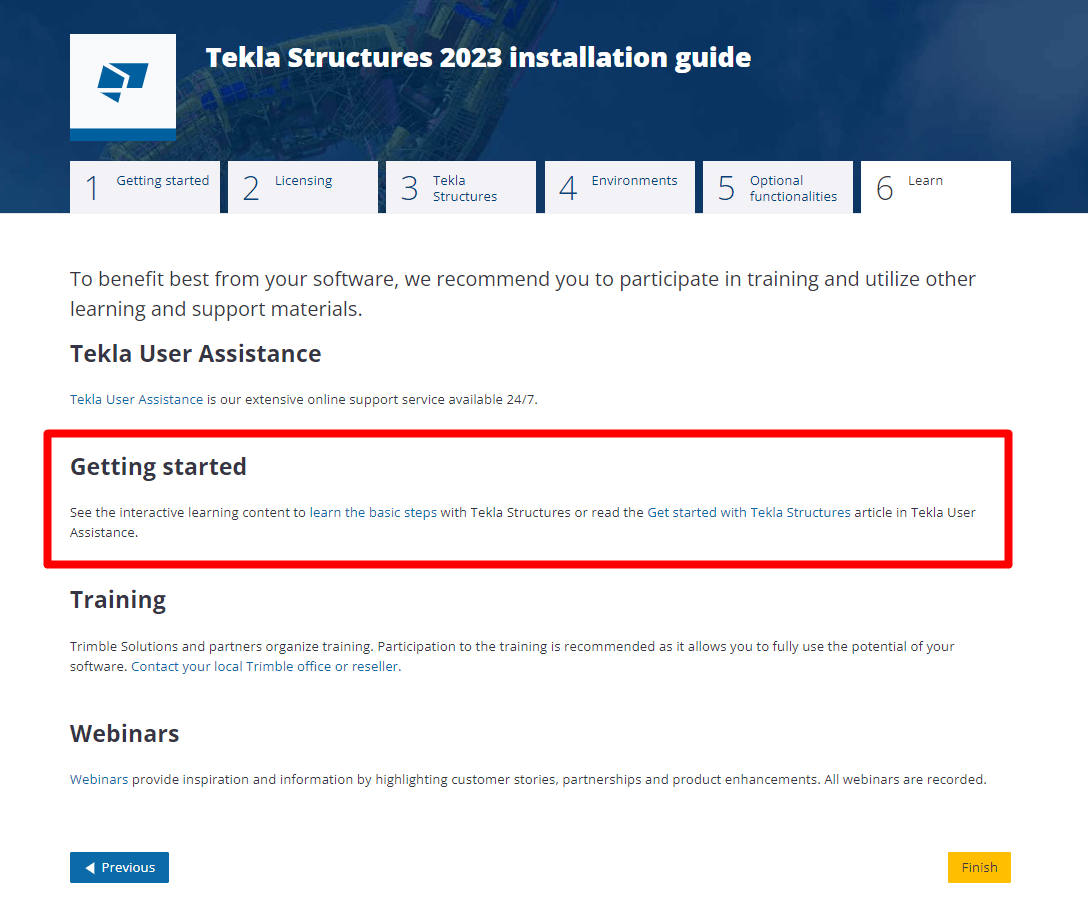
04 Learning Tekla Structures Through Tekla’s Basic Steps Videos:
Tekla Structures offers “basic steps” videos upon download. These are an excellent starting point for beginners, offering an official introduction to the software. Some companies combine these videos with additional training to bridge gaps in knowledge.
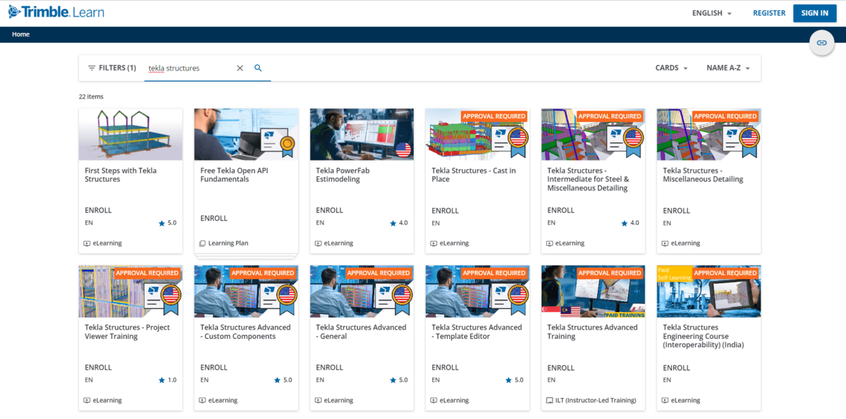
05 Learning Tekla Structures on Trimble’s Official Platform
You can explore Tekla Structures courses on the official Trimble platform, learn.trimble.com. The courses available vary in terms of accessibility. Some are freely accessible to all, while others may require approval from the creator, and there are also paid courses.
One advantage is the diverse language options available for courses. However, the sheer number of courses can be overwhelming, making it somewhat confusing to choose the right one. Furthermore, most of these courses are categorized as “free courses,” which is excellent if you’re on the path of “learning for free.” This can serve as the next step after grasping the basic concepts, helping you fill in any gaps in your knowledge.
06 Learning Tekla Structures Through YouTube Videos
YouTube is a valuable resource with a plethora of Tekla Structures content. While it’s free and rich in information, the vast amount of content can be overwhelming. Recommended channels can provide structured guidance, so here are some of the best:
- Tekla Structures (Trimble) official channel
- Tekla Structures (Trimble) official channel “Monday Minutes” videos list
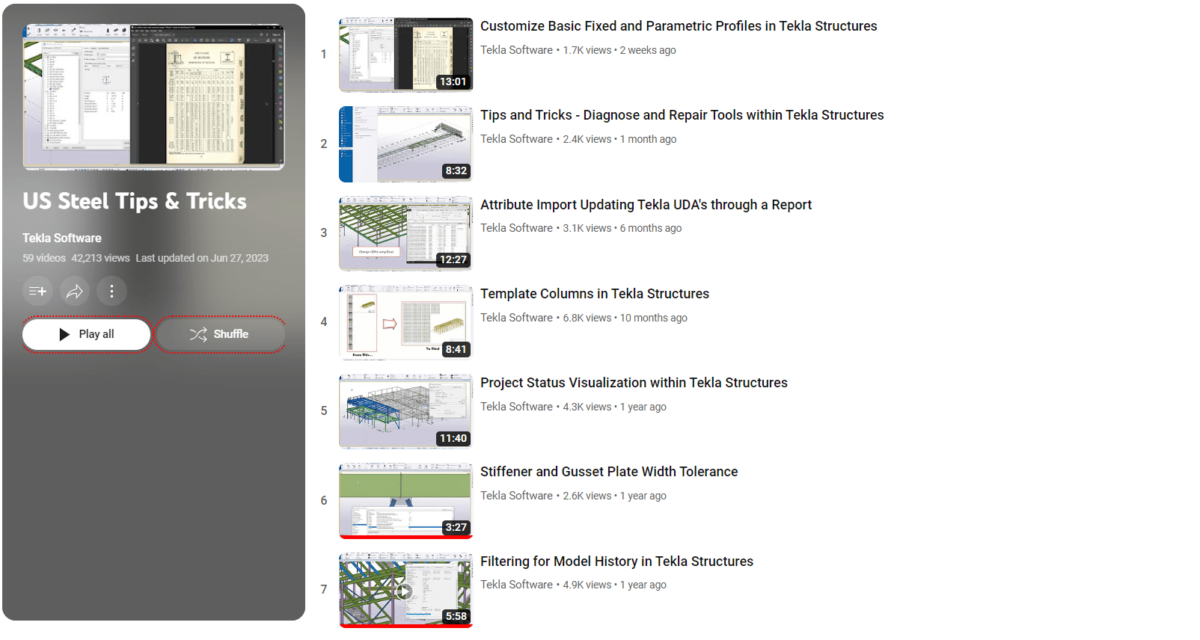
- Tekla Structures (Trimble) official channel “US Steel Tips & Tricks” videos list
- TSGuide channel
- BuildingPoint Australia channel
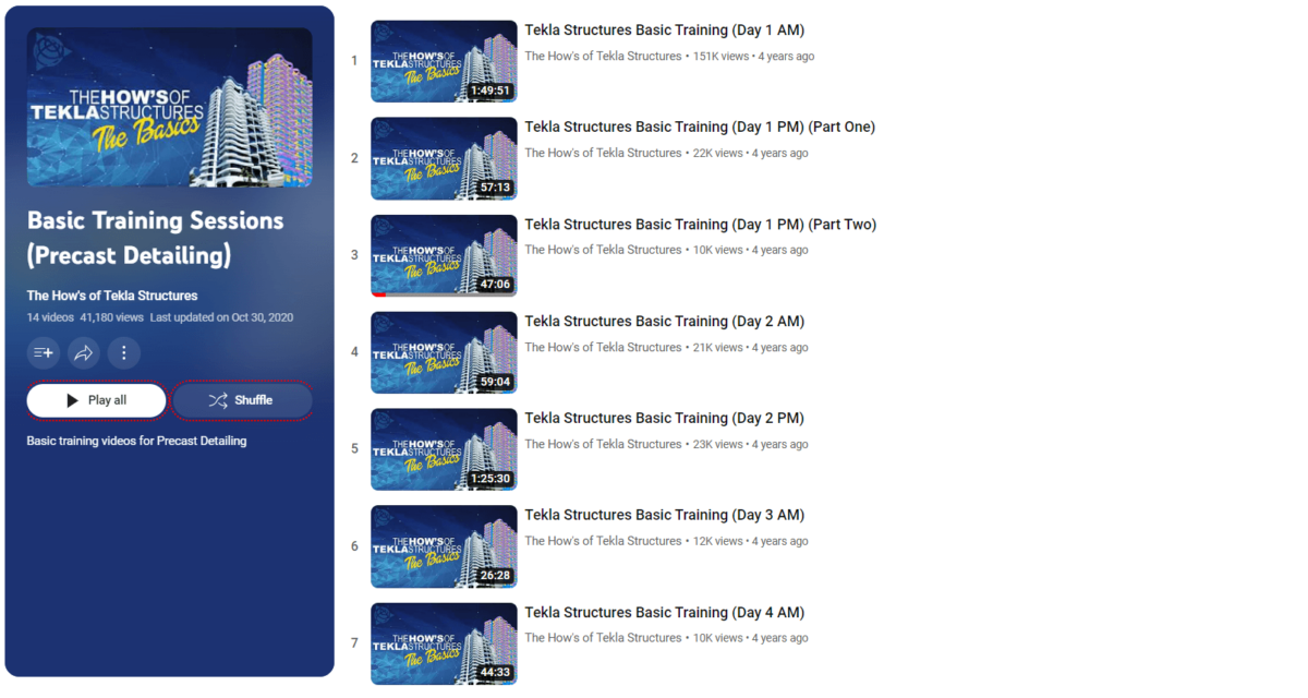
- The How’s of Tekla Structures channel
- The How’s of Tekla Structures channel Precast Basic Training Sessions videos list
- CS Wilson Draws channel
- Christopher Keyack channel
- Gani sk channel
- Maurice Dimba channel
- Construsoft España – Latinoamérica channel (in Spanish)
YouTube is quite good for finding answers to specific questions and it gives the answers in an easy-to-understand video format.
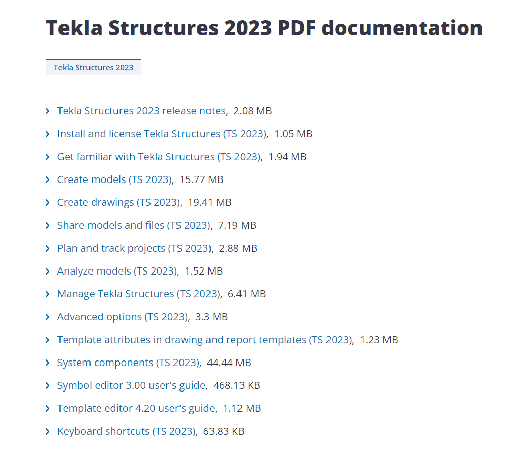
07 Learning Tekla Structures Through PDF Manuals
Trimble provides comprehensive PDF manuals for Tekla Structures. These are a great option if you prefer written materials. They offer a quality resource to grasp the basics of Tekla Structures.
I personally got bored after 20-30 pages. Still, keep in mind that it’s free, and the quality is quite good to get some level with Tekla Structures.
Different Ways To Level Up Your Tekla Skills
All the aforementioned methods are effective for starting your Tekla Structures journey. To further enhance your skills, consider these options:
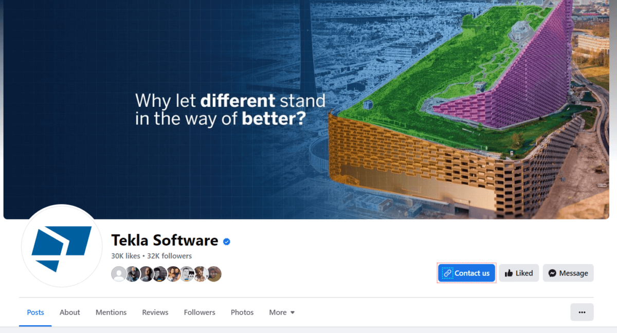
08 Level Up Through FaceBook
While Facebook can be informative, it’s not the most recommended platform for Tekla learning. Few groups may share valuable content, but many tend to focus on spam and promotions.
Still, there are three groups that you could follow:
09 Level Up Through LinkedIn
LinkedIn is a better platform for professional content sharing. Follow Tekla experts who share valuable tips and tricks.
Some of my recommendations to follow are:
- Trimble Tekla official
- Sten Tuudak
- Ali Ezz
- Duy Trung Vu
- Sriram Santhanam
- Lee Snyder
- Dawid Dyrcz
- Samuel Thapelo Mofokeng
- Alexey Perezhogin


10 Level Up Through Tekla Support Videos
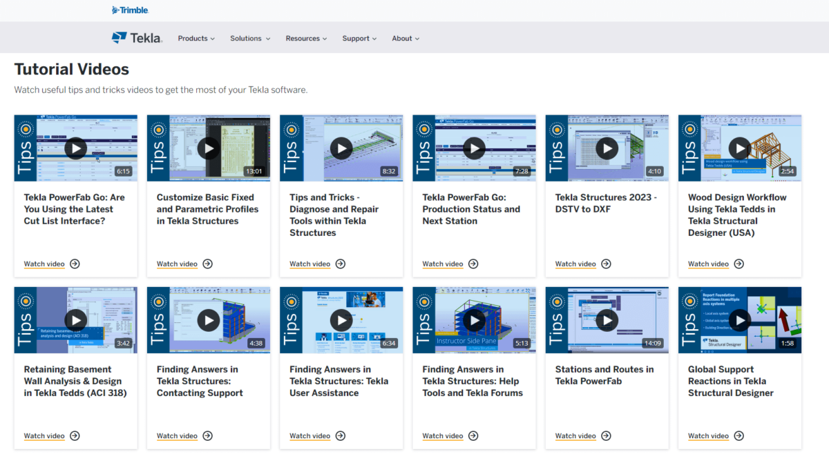
Tekla Support Videos offer a wide library of tutorial videos covering various aspects of Tekla Structures.
There are a lot of videos focussed on tips and tricks that are very useful:
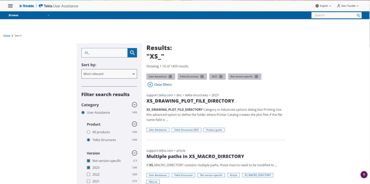
11 Level Up Through Trimble Tekla Support Articles
Trimble’s support site features extensive technical articles that provide in-depth guidance on Tekla Structures. This is an excellent resource for finding answers to specific questions.
Different from YouTube, there aren’t many videos – mainly articles. But on the other hand, the quality of content is controlled by almighty Trimble itself. It has really good quality and also includes minor details that some other sources may miss.
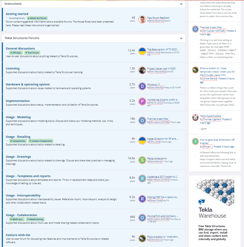
12 Level Up Through Tekla Discussion Forums
The Tekla Structures Discussion Forum serves as a community for Tekla users to interact and share experiences, tips, and tricks.
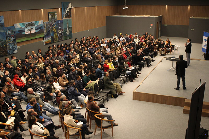
13. Level Up Through Tekla Live Events
Participating in Tekla live or online events offers opportunities to learn from experienced professionals, witness demonstrations of the latest features, and interact with the community.
Attending Tekla Live events allows you to learn directly from experienced Tekla professionals who can provide insights that textbooks or documentation may lack. Additionally, you can ask questions and get them answered in real-time.
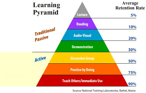
BONUS. LEARN BY DOING
Practical application is crucial. While theory and resources are important, active practice on real projects is indispensable. Learning through experience, assisting others, and seeking guidance when needed are key to mastering Tekla Structures.
TO SUM UP
To harness the full potential of Tekla Structures, it’s imperative to have a comprehensive understanding of the software’s functionalities. In this article, we explore various options for learning Tekla Structures, each with its own set of advantages and drawbacks.
Premium paid courses usually deliver the best results fastest but might be financially out of reach for some. On the other hand, cost-effective and free courses offer a budget-friendly entry point but provide only fundamental knowledge. While it may not suffice for mastery, it serves as a valuable foundation, far better than having no knowledge at all.
Live training offers personalization and immediate feedback, but it comes with a few disadvantages when compared to online training. Conversely, non-course resources often lack structured guidance, making it challenging for beginners to know where to start or what to explore next without overlooking essential aspects, potentially consuming a significant amount of time.
If I were to recommend an ideal path for a close friend, I’d suggest enrolling in a high-quality online course, such as the TSAcademy online course. Thoroughly work through the material at your own pace, gaining a substantial (about 80-90% of everything you need to know) understanding. Following that, consider investing a few hours in a consultation with an expert from Trimble or another trusted field specialist to address any lingering questions. With this comprehensive approach, you’ll be well-prepared to tackle your initial projects successfully.
Remember, consistent practice and ongoing learning will transform you into a Tekla expert in no time 😊 Keep in mind that getting started is often the most challenging part, but once you set the wheels in motion, your journey will progress smoothly.
AUTHOR
WAS USEFUL? SHARE WITH OTHERS
[Sassy_Social_Share_Pro]
YOU MIGHT ALSO LIKE


Tekla Structures stands as a pinnacle of 3D Building Information Modeling (BIM) software, greatly valued in the field of structural engineering. This software enables the design of a wide array of structures, spanning from buildings and bridges to conveyors, harbors, statues, and more. The versatility of Tekla is its key asset, as it allows for the creation of structures in various materials, such as steel, concrete, or composite combinations. Some companies even use it for materials like timber, aluminum, and glass structures.
Tekla Structures serves as a robust solution for design, detailing, and information management from the earliest conceptual planning phases to the fabrication and on-site construction.
When describing Tekla Structures, three key attributes come to mind: Efficiency, Detail, and Precision.
What is BIM (Building Information Modeling)?
Tekla Structures is a BIM software, and to grasp its significance, one must first comprehend the concept of BIM. BIM, an acronym for Building Information Modeling/Management, is more than just a single tool like Tekla; it constitutes an entire workflow and process. At its core, BIM leverages information-rich 3D models as a foundation.
BIM serves as a collaborative platform throughout the construction process, involving architects, engineers, builders, managers, planners, clients, and supervisors. This collaboration results in more informed decisions, leading to increased efficiency and cost-effectiveness in building projects.
Let’s delve deeper into BIM by breaking down each of its letters:
B for Building: Although Tekla can be used for various designs, the primary focus remains on building design.

I for Information: Information is a fundamental component of BIM. It includes various data associated with structural elements, such as names, position markers, weight, materials, dimensions, volume, environmental characteristics, fabrication dates, transportation details, costs, and maintenance information. This information can be automatically generated or added manually, and it can be exported through IFC models or displayed on reports and drawings. It´s everywhere updated automatically every time a change happens in the model. So, everything is up-to-date. Always!
M for Modeling/Management: BIM software allows you to create 3D models of structures, and these models can be exported in the globally-used IFC file format. This contrasts with traditional 2D CAD software, where drawings must be created by drawing individual lines. In BIM software, 3D modeling is not only visually appealing but also aids in better understanding the project and identifying errors.
The software often includes checks for detecting mistakes that might be missed by the human eye. Many Tekla Structures users attest to the improved quality and efficiency it brings to their projects, even if the time-saving aspect becomes apparent after gaining experience and fine-tuning software workflows.
What is Tekla Structures?
In a nutshell, Tekla Structures is specialized structural engineering software designed for construction industry professionals, particularly structural engineers. This software empowers users to create information-rich 3D Building Information Modeling (BIM) models, enabling them to design and model structures of various sizes and complexities. Tekla Structures excels in handling materials such as steel, concrete, bricks, timber, aluminum, insulation, and composite structures with exceptional precision and detail.
In the construction industry, attention to detail is crucial. The Level of Development (LOD) standard, which measures the level of detail in a BIM model at a given point in its design process, is widely recognized internationally. It encompasses not only graphical objects but also the associated data. The LOD levels range from 100 to 500, signifying different stages in the design process:
- BIM LOD 100: Conceptual Design
- BIM LOD 200: Schematic Design
- BIM LOD 300: Detailed Design
- BIM LOD 350: Construction Documentation
- BIM LOD 400: Fabrication & Assembly
- BIM LOD 500: As-Built and Building Operations
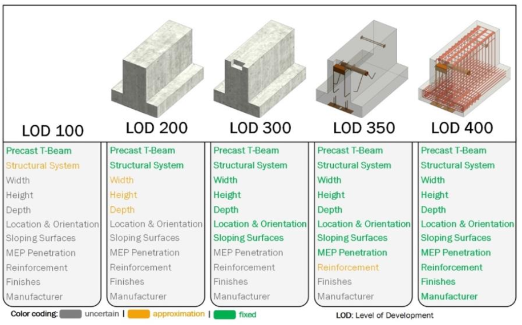
Tekla Structures is capable of projects at LOD 400, implying that it models every element needed for fabrication and assembly, down to assembly elements, insulation, plates, welds, rebars, couplers, bolts, and more. Furthermore, it can achieve LOD 500 with even more comprehensive information.
One of the remarkable benefits of Tekla Structures is its interconnectedness. When modifications are made in the model, all associated drawings are automatically updated, ensuring accuracy and consistency. In contrast, modifying 2D CAD drawings requires changes to be replicated across multiple drawings, introducing opportunities for errors.
Tekla Structures incorporates intelligent tools and components, ensuring that changes to a profile or element shape automatically propagate to linked parts, connections, and reinforcements. Additionally, a wide array of modeling tools and connections are available within Tekla Structures, with the Tekla Warehouse providing additional plugins and extensions.
For those seeking further customization, Tekla allows the creation of Custom Components without the need for coding, streamlining manual tasks and automating workflows. In fact, Tekla Academy offers training on creating Tekla Custom Components, which can be learned in just one day.
Notably, Tekla Structures exhibits excellent interoperability with parametric modeling software like Rhino Grasshopper, and for those proficient in C# coding, it opens the door to custom developments using OpenAPI.
Leveraging these intelligent tools enhances work speed, efficiency, consistency, and error reduction. While the bulk of tasks can be accomplished with these tools, there will always be situations where manual fine-tuning is required, offering limitless possibilities for customization.
Tekla Structures allows users to create information-rich 3D BIM models and extract 2D drawings in DWG or PDF format, produce Excel reports, IFC models, and special file formats (e.g., .NC and .BVBS) for use with fabrication machinery or Enterprise Resource Planning software. Notably, Tekla Structures is known for its openness and collaboration with other software, hardware, and industry partners.
However, it’s essential to note that while Tekla Structures offers features for project planning, it is not an Enterprise Resource Planning (ERP) software, nor does it perform structural calculations. Nonetheless, it can integrate seamlessly with various calculation software.
Who Benefits from Tekla Structures?
Tekla Structures primarily targets structural engineers within the construction industry. It is also favored by steel detailers, fabricators, precast fabricators, rebar fabricators, cast-in-place concrete contractors, and a wide range of planners and project managers who find value in its capabilities.
However, it’s crucial to understand who Tekla Structures is not intended for. Architects and MEP (Mechanical, Electrical, Plumbing) engineers may find that the software, while powerful, is not aligned with their specific needs. Tekla Structures is oriented toward structural modeling and design rather than the aesthetic aspects of construction.
What Does a Tekla Structures License Cost?
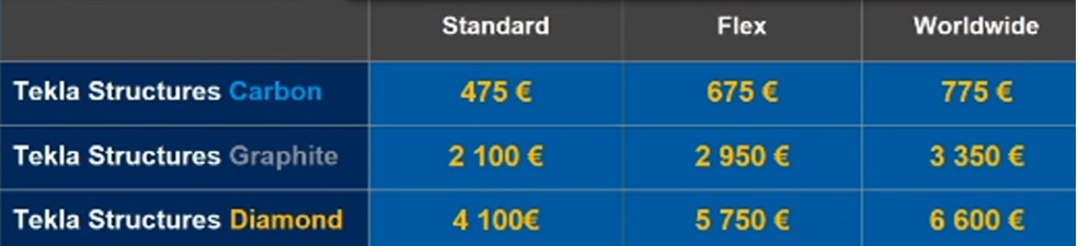
Tekla offers three types of licenses, each with different plans and costs. Understanding these options is essential for users looking to acquire Tekla Structures licenses:
Carbon License (Viewer License): This is the most basic option and is primarily for viewing and collaboration on models. It does not support modeling or creating drawings and is often used by project managers and planners.
Graphite License: Positioned between the basic and full licenses, the Graphite License allows modeling but comes with certain limitations. For example, users can model with conceptual components, but numbering is not supported. This means that modeled elements won’t have position numbers, making it unsuitable for fabrication drawings. Nevertheless, it is suitable for creating General Arrangement drawings, including plans, layouts, and section views.
Diamond License (Full License): This is the most comprehensive and powerful license, providing access to all features and capabilities of Tekla Structures. Engineers who require end-to-end control, including the production of fabrication drawings, typically opt for this type of license.
See the full list of features and possibilities that different licenses offer HERE.
It’s important to note that license types may vary based on your region and may come with specific terms and conditions. Tekla Structures no longer offers perpetual licenses with separate maintenance and version update fees; instead, licenses are typically available through yearly subscription plans. These subscription plans may be categorized as Standard, Flex, or Worldwide, offering various levels of flexibility in transferring licenses between users or locations.
To get official price offer and purchase your licenses, you need to contact to your local Tekla offices and retailers.
Getting Started with Tekla Structures
For those looking to explore Tekla Structures, a 30-day free trial version is available. If you aim to continue learning and practicing, Tekla offers a free student license that can be extended as needed. However, these licenses are intended for educational purposes and are not suitable for professional projects.
In the end, there is the link to a quick an overview of “First steps with Tekla Structures” or if you plan to do a more serious study, then I recommend TSAcademy and take the basic user full guide.
System Requirements for Tekla Structures
Before delving into Tekla Structures, it’s important to ensure that your computer meets the software’s requirements. Notably, Tekla Structures is compatible only with Windows-based systems, and Mac users may need to use a Windows emulator or alternative solutions.
Here are the essential system requirements for running Tekla Structures:
- Operating System: Tekla Structures is optimized for Windows 10 (64-bit). While newer Windows versions are available, Windows 10 is widely regarded as stable and user-friendly.
- Memory (RAM): A minimum of 16GB of RAM is recommended. The memory requirement can vary based on your usage, so ensure your system has sufficient RAM to accommodate Tekla Structures and other applications. It’s worth noting that web browsers, particularly Google Chrome, can be memory-intensive.
- Hard Disk: It’s advisable to have at least 1TB of storage. Maintaining free space is critical for smooth operations. The choice of hard disk type matters; solid-state drives (SSD) or NVMe M.2 drives are recommended for speed and efficiency.
- Processor: Tekla Structures tends to benefit more from higher clock speeds than multiple cores. Processors like Intel Core i7 (3+ GHz) and Intel Core i9 (4+ GHz) are suitable for running the software efficiently.
- Graphics Card: While a powerful graphics card is beneficial, specific models can vary. Nvidia RTX 2xxx or 3xxx series cards are recommended for optimal performance. Tekla maintains a list of tested graphics cards for reference.
To evaluate how well a computer can handle Tekla models, Tekla provides a performance-measuring tool. By running this tool on various computers, you can gauge their suitability for running Tekla Structures.
Tekla’s Interoperability with Other Software
Tekla Structures is known for its open approach to interoperability, enabling seamless collaboration with various file formats and other software. Here are some key aspects of Tekla’s interoperability:
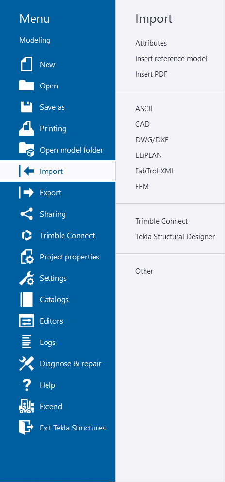
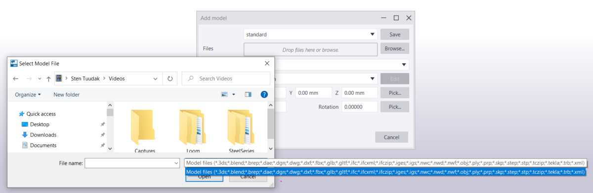
Importing References: Tekla allows for the import of references from various file formats, such as .dwg, .dxf, .pdf, and .ifc. This capability aids in the initiation of projects and ensures compatibility.
Transferring to Analysis Software: While Tekla Structures is not a structural analysis software, models can be transferred to dedicated analysis software, enabling in-depth structural analysis and simulations.
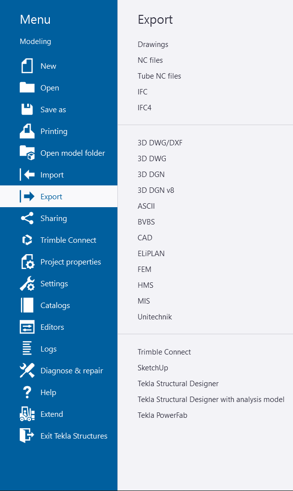
Exporting Drawings: For standard project requirements, Tekla facilitates the export of drawings in .dwg, .dxf, or .pdf formats, which are essential in the construction industry.
Fabrication Files: Tekla supports the generation of .nc files in DSTV format and .dxf files, which are particularly valuable for CNC machines used by steel fabricators.
Specialized Formats: For specific applications, such as rebar cut and bend machinery, Tekla enables the creation of .bvbs files. Additionally, hollow core fabricators can work with EliPLAN files, while automated wall panel fabricators can use unitechnik files.
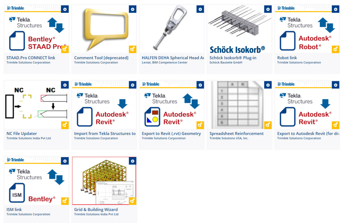
If you search in Tekla Warehouse “direct link” then you get these plugins to connect directly with Tekla Structures:
For smooth integration with Tekla Structures, a range of plugins is available, enhancing connectivity and workflow optimization. The common .ifc file format serves as the lingua franca for data exchange between different software applications.
Most of other cases, *.ifc file format is still the common language between different software.
An official full list of compatible file formats and software with Tekla Structures you can find from HERE.
In addition to standard interoperability, Tekla Structures offers the potential for custom development through its OpenAPI. This feature allows for the creation of tailored solutions, enabling more advanced integration with specialized tools and processes.
Tekla Structures’ Advantages and Disadvantages Compared to Other Solutions
Tekla Structures offers numerous advantages, making it a leading choice for structural engineering in the construction industry. Its features and capabilities, along with its open approach to interoperability, set it apart. Some of its key advantages include:
- Advanced 3D Modeling: Tekla Structures provides robust 3D modeling capabilities for designing complex structures.
- Materials Flexibility: The software supports the design and modeling of structures using a variety of materials, including steel, concrete, wood, glass, and more.
- High Accuracy and Detail: Tekla Structures delivers high precision and detail in models, crucial for ensuring structural integrity.
- User-Friendly Interface: The software features an efficient and intuitive interface, streamlining the modeling of intricate structures.
- Automatic 2D Drawing Generation: Tekla Structures can automatically generate 2D drawings from 3D models, facilitating the creation of floor plans, sections, and detailed elements.
- Interoperability: Tekla Structures seamlessly integrates with other construction-related software, including BIM and CAD tools.
- Collaboration: The software supports collaboration and information sharing among different stakeholders involved in a project.
- Global Support: Tekla maintains offices in many regions, ensuring accessibility and support for users worldwide.
- Support for Multiple Languages: Tekla Structures supports up to 16 languages, accommodating users from various linguistic backgrounds.
While Tekla Structures offers numerous advantages, there are a few considerations:
- Initial Learning Curve: Some users may find Tekla Structures complex and challenging to learn, particularly at the outset. However, proficiency typically improves with experience.
- Cost: Tekla Structures is generally more expensive compared to some other software solutions. Smaller companies with budget constraints may find it less affordable.
Despite these considerations, the advantages of Tekla Structures are often seen as outweighing the disadvantages, particularly for professionals and organizations that require advanced structural engineering capabilities.
The History of Tekla Structures
The history of Tekla Structures dates back to the founding of Tekla OY in 1966 in Helsinki, Finland, by Reino Heinonen. The name “Tekla” is derived from the Finnish words “Teknillinen Laskenta,” which translates to “Technical Calculation” in English.
In 1993, Tekla Structures was introduced as the structural engineering software, initially known as XSteel. XSteel marked a significant milestone for Tekla OY, becoming the company’s most exported product, reaching 38 countries.
In 2004, XSteel was officially rebranded as Tekla Structures, solidifying its position as a premier solution for structural engineering.
In 2011-2012, Trimble Inc. acquired Tekla OY for $450 million. This acquisition strengthened Tekla’s position within the construction industry and enhanced its global reach and capabilities.
Today, Tekla Structures is widely available and used around the world by professionals in the construction industry for designing and modeling complex structures.
What other software does Trimble offer?
Over time, Tekla OY, and later Trimble corporation, has developed themselves or acquired different softwares to have a more complete offering.
Model Sharing is a separate service that Tekla Structures users can purchase. Out of the box Tekla has a multi-user option that allows different engineers to work together on one project. With Model Sharing this coworking has been made much easier, faster, and distance is not an issue anymore. If your company has projects where different engineers need to work together, it’s the service you most probably want to consider taking.
Trimble Connect is another cloud-based service that helps with collaboration. If Model Sharing was helping only the engineers who are working in Tekla Structures, then Trimble Connect is something that brings together everyone who are connected with the project. Basically, it’s a cloud-based storage like a Google Drive or Dropbox, where you can keep all the files related to a project, but it’s specifically made for construction industry. For example, everyone can view all the 3D BIM models in their browser, set elements statuses and communicate using notes and tasks.
Sketchup is another 3D design solution that works on web.
Tekla Tedds is a simple structural analysis software that replaces simple Excel or MathCAD calculation sheets. It’s similar, but made specifically for doing structural calculations.
Tekla Structural Designer is also a structural analysis software, but this one can do much more advanced Finite Element Method calculations.
Vico Office is all about project planning and management controlling the time and money factors. They are called also as 4D and 5D.
Trimble RealWorks is point cloud processing and analysis software for 3D laser scanning professionals. BTW in Trimble portfolio there are many top level laser scanners.
Trimble MEP is something for mechanical, electrical, and plumbing engineers.
Tekla PowerFab is an Enterprise Resource Planning software for steel fabricators.
There are much that Trimble has in their portfolio, but these are the tools that I know about 🙂
Notable Projects with Tekla Structures
Tekla Structures has been used in numerous high-profile construction projects around the world. Some notable examples include:
- Hudson Yards, New York City, USA: The Hudson Yards development, one of the largest real estate projects in the United States, relied on Tekla Structures for the structural steel detailing and coordination.
- Beijing Daxing International Airport, China: This massive airport, known for its distinctive starfish shape, used Tekla Structures to manage the intricate structural and steel detailing requirements.
- Mersey Gateway Bridge, UK: The construction of this cable-stayed bridge, which spans the River Mersey between Runcorn and Widnes, utilized Tekla Structures for modeling, fabrication, and construction planning.
- King Abdulaziz Center for World Culture, Saudi Arabia: This cultural center, also known as Ithra, featured complex architectural forms, and Tekla Structures played a crucial role in detailing and fabrication.
- New York Wheel, USA: The New York Wheel, which aimed to be the tallest observation wheel in the Western Hemisphere, relied on Tekla Structures for its complex structural detailing.
These projects highlight Tekla Structures’ capacity to handle a wide range of construction challenges, from complex architectural designs to large-scale infrastructure projects.
Conclusion
Tekla Structures stands as a prominent 3D BIM software solution for structural engineers and professionals in the construction industry. It offers advanced 3D modeling, high accuracy, and interoperability with other construction-related software. Its historical significance and notable projects highlight its importance in the field of structural engineering and construction.
For users, understanding its licensing options, system requirements, and the potential learning curve is essential. While Tekla Structures may have specific costs and complexities, its advantages often outweigh these considerations for professionals and organizations seeking a robust solution for structural design and modeling. As the construction industry continues to evolve, Tekla Structures remains a key player in the realm of BIM software.
If you have any further questions or need additional information about Tekla Structures or related topics, please feel free to ask!
AUTHOR
FIND THIS USEFUL? SHARE IT!
[Sassy_Social_Share_Pro]
YOU MIGHT ALSO LIKE

Tekla Podcast episode #4 is the second session with Artis and Jānis from UPB, a Latvian company that has been around for about 30 years. They specialize in integrated solutions for complex constructions, and with almost 200 engineers on the books it’s no wonder they have been a continued success in the industry.
Just in case you didn’t check out podcast #3, Artis Aizstrauts is the head of R&D of UPB; an accomplished researcher with over 20 publications to his name, and Jānis Goldmanis, is an R&D Project Manager with more than 9 years’ of Tekla Structures & engineering experience.
Watch the whole interview video here:
ARVE error: Mode: lightbox not available (ARVE Pro not active?), switching to normal mode
or listen it in audio format here:

Don’t have time to watch the whole pod? Skim the questions and answers summary in a written format below! 👇
Why did UPB go into this segment of doing aluminium facades, and especially with Tekla Structures?
Jānis: We had been doing 2D drawings in Autocad as recently as 3 years ago, and the projects were getting larger and more complex. In the facade sector, there are so-called “System softwares”, where each manufacturer of that profile system has their own system software, where you simply input the width and the height of your element. And the software will then output everything that is necessary.
But these larger projects normally require custom solutions – systems from the catalog are not good enough. Because of this, if we were not using the system software, then instead we were using Autocad, where everything needed to be done manually.
As mentioned, with the projects getting larger and larger, we knew we had to make a change. We evaluated several different systems including Revit, Tekla, Solidworks, and more.
Each had their advantages and disadvantages, naturally. But in the end we went with Tekla – partly because we were more familiar with it – but also because of how customisable it is.
There are two main benefits that helped sway our decision: first of all, Tekla is capable of handling very large models, and additionally, those models themselves could be very detailed.
It has to be said that perhaps out of the box Tekla wasn’t the best at detailing for facades. For example, if you look at Solidworks, it’s much more suited to fabrication, but it is only capable of handling one single element. Whereas Tekla was capable of holding the entire model.
We also evaluated the customization options available via API, and we decided that we would be able to customize it to the needs of our facade division.
API developments – why did you go down that route?
Artis: Firstly, in Tekla you can model whatever you want – OK, fine. But the big question when it comes to facades is how. They are so much more complex than concrete and steel. There were a lot of questions that needed answering. So, we created an R&D team specifically to help implement Tekla in the facade unit.
The team was comprised of Tekla experts from our Heavy (steel and concrete) division, and facade experts. The facade experts know what needs to be done to produce the final product. The Tekla experts know how much is possible to be done in Tekla.
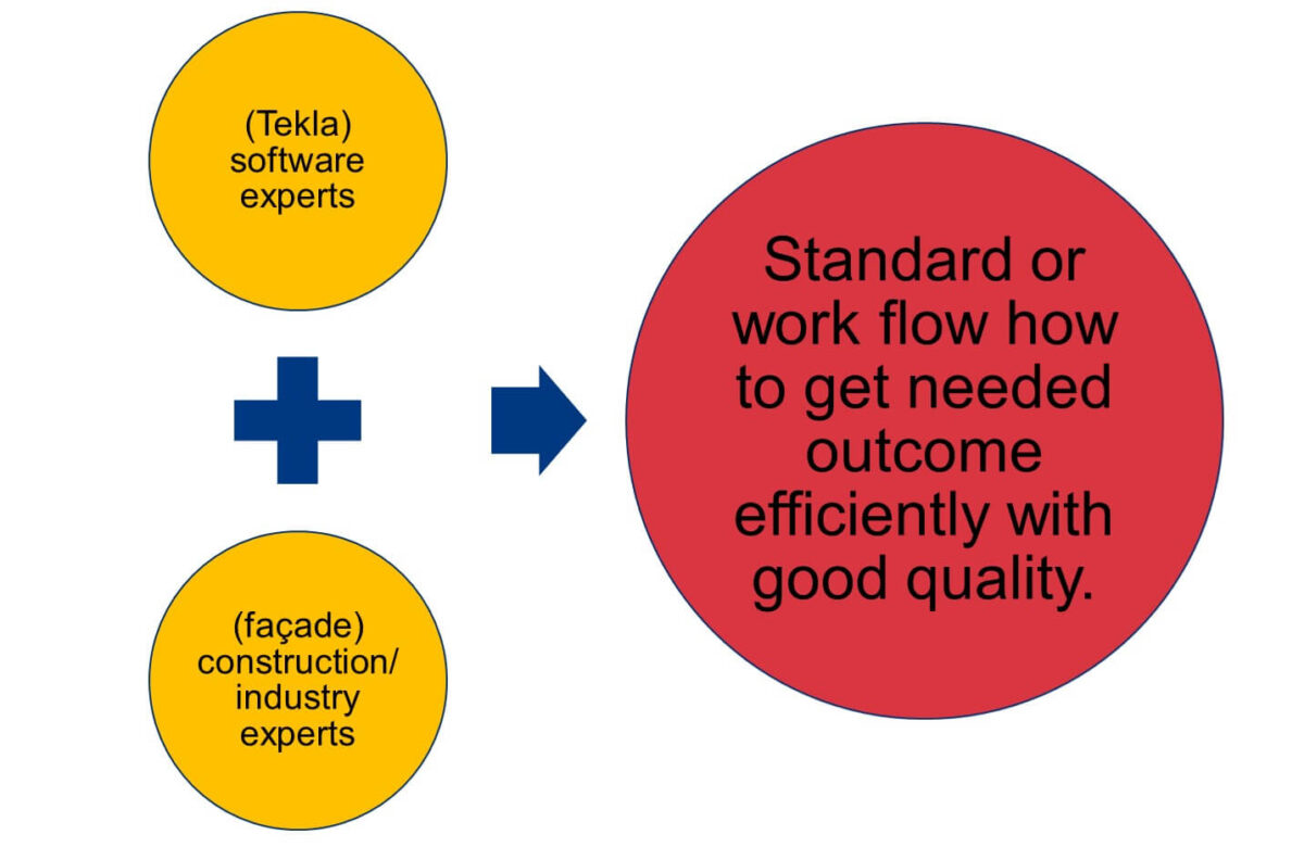
Based on the knowledge of these two halves of the team, we developed our own standard for modeling facades in Tekla. Once we had the standard (documentation), we developed tools to do it all faster, and then we were able to start switching to Tekla in the facade unit. It was a very sensible approach to implementation, and doubtless saved us a lot of time.
Using these tools, how much faster does the work take now compared to when Tekla was first used? What are the struggle points that they still have?
Jānis: It can be hard to put it into exact numbers! What we do know is that in the beginning, things were naturally a bit slow as we all got used to the new methods. But, after 3 or 4 projects, we already knew that we were working at a similar speed compared to when we were using Autocad. But the difference was day and night with what we were actually doing.
The time saving and benefits (for example, the time it takes to generate quantity take-offs) of working in a new way don’t increase linearly with the increase in the size of a project. It increases exponentially.
With Autocad, we were limited to projects that consisted of something like 500 elements. That is, that’s as big as the project could be, and still be somewhat manageable.
With Tekla, we have done projects with 3000 elements. It’s still very manageable within one very large model. Also, it isn’t just about the speed; the main point is that we have enabled this process that allows us to handle a project so large. With the same team, we can now manage projects 6 times larger than before. With Autocad, it would be impossible.
Now that we are more experienced and have completed a lot of projects, and we’re learning even more advanced methods and developing new tools, the speed also increases. I’d say that now, even the speed is faster than it was before with Autocad. And even then, that isn’t the most important benefit.
The biggest benefits realized have been the scale of projects that we can undertake, and the amount of useful information that can be created to go along with it to pass down the line-manufacturing, logistic, assembly.
Can you give us some examples of using information like elements size, weight, and location to plan installations and transportation?
Jānis: When the engineers produce a model, it tends to be a rough sketch. However, this includes information such as the overall size of the elements, and their locations.
This data is immediately accessible to the assembly team as a 3D model, and straight away they can start planning the installation sequence together with the project manager.
That information immediately arrives at the factory, and in turn they can plan the manufacturing processes. Since they already know the rough sizes of the elements, what kind of profiles, what kind of bars are needed, and so on.
For facades, the material orders are very important, since some of them can take as long as 3 months to arrive. So, having that information as soon as possible is a huge plus.
Also unique to facades is that the materials required are generally very expensive; much more so, relatively speaking, than precast concrete or steel. We need to be particularly efficient with materials ordering for manufacturing, and from the 3D models we can very quickly extract data about what is needed.
For example, say there are 20 km of aluminium profile in the facade, we can immediately optimize how many bars, and in what length, that need to be ordered.
Add to this, that at any moment, the assembly sequence can change, for a number of reasons. For us, it’s now easy to deal with, since we get the new installation sequences from the assembly team. Then we can re-optimize the materials, and change the manufacturing order, so that everything is done efficiently.
“We calculated that quantity take-offs using DWG took around ~17% of an engineer’s time; in Tekla, it’s almost immediate.”
Can you show us an example of how you are creating aluminium facade elements in Tekla?
Editor’s note: This part of the interview is really best enjoyed by watching the video. Jānis goes on to demonstrate a host of tools that they have developed in Tekla for all sorts of amazing efficiency gains. Check it out!
How was it in the beginning to start doing these aluminium facade elements manually?
Jānis: There was a lot of experimentation in order to find the correct approach! As mentioned earlier, we have developed our standards, but in order to develop them, we had to go through different iterations of models, and different projects where we tried different approaches.
For example, with the very first model, all of us were Tekla experts. And we decided to go with Tekla’s custom components. We created some very complex custom components. But, that didn’t work, and we had to finish the project using manual methods!
For the next project, we decided to replace these components with plugins. And now we know that to be the best option.
When would you recommend using custom components, and at which point would you change to OpenAPI?
Jānis: So, connections should definitely be custom components, since they’re unique from project to project, and it’s almost impossible to make a comprehensive plugin that solves everything. The connection creator I showed in the demo which made these fittings – well, that is its sole purpose.
If you need to do some custom bolt connections with the inside connectors, the idea is that you make it as a custom component, and then you import it within this tool. You should definitely think about doing plugins if you have creation criteria.
In some places you need to create something, and in others, you don’t. For example, this unitized frame; normally with unitized elements, they look the same – but in fact, they have some small differences.
For example, every second element doesn’t contain the middle vertical beam. This needs to be produced either by two custom components, or a plugin that can handle all of the cases; it shouldn’t be one complex component.
Also, a very big no-no is creating complex parametric custom components within parametric custom components! It will collapse very quickly; your project will stop working as expected. Having a simple “Array” component working inside your custom component is ok.
How much time and effort have you put into these custom components and these API plugin developments?
Artis: It’s more or less 4000 man-hours over the course of around 3 years. If we remove the huge experience in Tekla or facades, well you can’t do that only with developers. The developing part is the easiest; what took the largest amount of time was the “how” question.
As I mentioned earlier about the standards and methods of creating the model and its structure – this is where a lot of time was taken. Determine and finalize things like what is the assembly, what is the component, what is the plugin, and so on.
As Jānis mentioned, at the beginning you may think “Yeah, that should work, because it worked with steel or concrete”. But as he said before, one element in a precast wall has how many details? Say, 20? But a facade element will easily come in at ten times that amount.
Trial and error was the only way to go, and that’s what clocked up the most hours out of that ~4000.
Where can people get access to these tools?
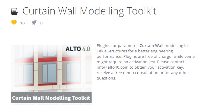
Artis: Yes, we have published them in the warehouse. You can get them from HERE. There is also a lot of supporting documentation and videos to go along with them.
Who would get the benefits from these tools, what kind of companies or customers should use these?
Jānis: Companies that are switching from 2D DWG (Autocad or any other similar software) to Tekla would get the most benefit from these tools. They won’t have to figure out all of these things themselves. They can start benefitting from our experience in a reasonable amount of time.
The alternative to that is that you need very experienced users who are capable of quickly creating complex custom components to replicate what we are doing with our plugins. What the tools achieve is to lower the bar of entry – the qualifications and experience required of the users.
Since, for precast and steel, I’d say the bar is much lower for what qualifications/experience an engineer would need in order to generate an optimal workflow. For facades, it’s much higher, and the plugins really help with this.
Your final recommendations: How to reduce project mistakes and raise efficiency?
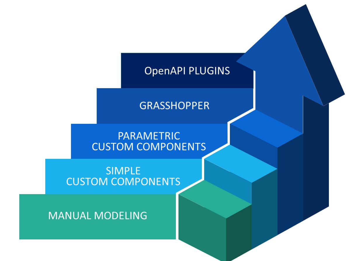
Jānis: Mistakes can be eliminated if you don’t try to do something more complex when you haven’t already learned how to do it with simpler methods. First of all, you should really learn Tekla’s basic functionality; so, do something manually.
Next, learn how to use automation in Tekla; how to make simple custom components, such as simple drawing templates.
Once you’ve mastered that, move up to parametric custom components. With more time and experience, you should then move on to considering introducing Grasshopper.

Don’t create one super custom component that does everything, because when something goes wrong, it will be very difficult find out where the problem is if things aren’t working as expected.
Instead, separate everything into small, modular steps; separate small custom components that combine together to achieve what is necessary for you.
Finally, never stop improving yourself. The more you learn, the more you understand how much you don’t know yet!
Go check out our last podcast episode also with Janis and Artis here.
AUTHOR
FIND THIS USEFUL? SHARE IT!
[Sassy_Social_Share_Pro]
YOU MIGHT ALSO LIKE


Podcast #3 features two key employees of UPB, a Latvian company that has been around for about 30 years. They specialize in integrated solutions for complex constructions, and with almost 200 engineers on the books it’s no wonder they have been a continued success in the industry.
Our first guest is Artis Aizstrauts who is the head of R&D of UPB; an accomplished researcher with over 20 publications to his name. The second guest is Jānis Goldmanis, an R&D Project Manager with more than 9 years’ experience.
Watch the whole interview video from here:
ARVE error: Mode: lightbox not available (ARVE Pro not active?), switching to normal mode
or listen it in audio format here:

Don’t have time to watch the whole pod? Skim the questions and answers summary in a written format below! 👇
When did you start with Tekla Structures, and what other systems did you consider?
Jānis: We started using Tekla in 2006, at which point all our design work was being done in AutoCAD, and there were two things that we needed to improve. First was our design accuracy, and the other was our design speed. Accuracy is obviously important, but more so for us because the majority of our work is exported (to Scandinavia), and it is very costly to fix design mistakes on site when all your resources are in Latvia, but you are working on a site in Sweden. Working with Tekla’s 3D BIM means that you can for example check much easier for clashes in your model using the software. Tekla ensures that our designs are much more accurate.
And then of course, speed. At the time, we were doing a lot of large parts with prefab steel construction, and Tekla is very good with this. The main reason being the numbering system, whereby you can simply model everything you need, and then Tekla automatically applies the numbering and tells you which parts are the same, meaning you can quickly reduce the number of necessary drawings. Prior to that, we were working with 2D DWGs, and we were basically creating drawings for each beam. This meant each beam had a unique set of parts; you didn’t check if the next beam was the same or not – you simply went on to the next one with another drawing. From experience, Tekla solved most of these issues, heavily improving design speed as well as accuracy.
3 years ago, we were also choosing software for our Facade division. It too was lagging behind, using the same 2D DWGs, but our projects were becoming more and more complex, to the point where they were becoming unmanageable. We were investigating whether Tekla was also a good solution for this scenario; comparing it against competitors like Revit and Solidworks. In the end, we went with Tekla again, because of the ability to create very large and detailed models. Despite the fact that the facade projects were much more complex than any steel or precast project. The other platforms we researched were either lacking the amount of detail, or the scale.
Do you remember how it was when you first started to use Tekla?
Jānis: In one word: Inefficiency! When we started there was a lot of trial and error going on just to figure out how to work with the software. Only a few people did any official training, and we had no internal processes in order to distribute their newly-acquired knowledge to others. As a result, everyone was slowly figuring it out themselves; how to work with templates, even just how to model simple things, how to create drawings, and so on.
Over the years we have figured things out. Then, 3 years ago when we were implementing Tekla in our aluminium curtain walls, I would say it was much faster. We already knew all of the basic Tekla functionality, and we simply put together a team of experienced Tekla users and experienced facade designers. Together we made different proposals of how we should model facades in Tekla. It took something like 3 iterations of models, and after each one we revised the approach. In the end it took around 9 or 10 months to determine the best way forward.
“There was a lot of trial and error going on just to figure out how to work with the software. Only a few people did any official training, and we had no internal processes in order to distribute their newly-acquired knowledge to others.“
If someone were to start a new company, how would you recommend they go about it?
Jānis: If you’re just starting out, I would recommend against trying to automate everything from the start. It definitely helps if you have an expert consultant who can show you the possibilities, but you should learn the basics of how Tekla works before moving to more complex things. If you jump too far ahead without a solid foundation of knowledge, you will inevitably make mistakes.
You mentioned different automations; what have you done over time?
Jānis: We have made an internal system for our precast wall panels – and we have a set of components that need to be used. We have an organized system whereby for example, when a user needs to do something with a wall panel, they will already know which components they need to use. There are also pre-set attributes that users can use very simply. Creating this organised system was the first thing that really helped us. Of course, you can’t make components for everything, but you could easily make them for 80% of what needs to be done.
What we are currently working on is working for the whole model. If we know the steps we need to produce one single element, we can then automate the steps required for thousands of those elements. We simply need to look at the model and figure out, what is the 80% here that we can automate?
You mentioned automations for an entire project rather than just some elements; how do you manage to do this?
Jānis: We’ve used Grasshopper; it’s a tool that allows you to quickly try your ideas. You can quickly create a concept that maybe isn’t foolproof, but it shows that it could work. And based on that, we are able to take things forward and make applications.
For example, 5 years ago, engineers needed to add lifting anchors to the wall panels. What usually needed to be done was to look at the unit properties in order to find the weight of the panel. They then needed to calculate the necessary resistance of the anchor, after which they would search the catalog for a suitable one, and then insert the anchor into Tekla.
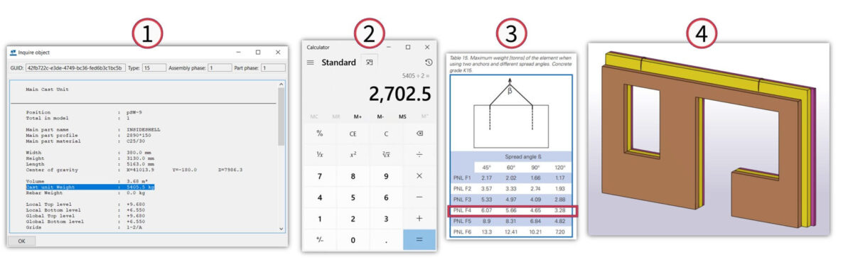
The first step to build this process was to create custom components for anchors in Tekla. Prior to this, everyone was simply creating their own models and naming them. So, we made the models available. Next, in order to make the process smarter, we exported all the cast unit properties to Excel, where we could then calculate all the necessary anchor types for each using a formula. This is where Grasshopper comes in. It easily reads this data, and then references a large number – thousands, easily – of wall panels in your model, then based on the data in the spreadsheet, applies the appropriate anchors to all of them in your model.
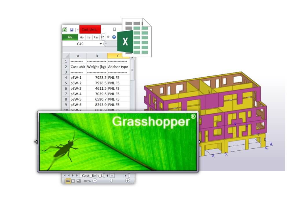
In the last step, we don’t even need the spreadsheet. All of the calculations end up being done in Grasshopper, you select your whole model, and then all the anchors would then be inserted automatically. Once we have refined it and ensured that the accuracy is up to spec, we created it as an application instead.
Now, this application inserts all the correct anchors according to the panel weight and the detailer just has to check for clashes.
To take things further, we are currently looking at each type of action that you need to perform on an element, for example, insert anchors, insert reinforcements, insert perimeter reinforcements, create seams and so on, and creating these automatizations for all of them so that we can do these actions for the whole model at once.
To illustrate it, one very useful tool, Connection Classifier, is available in Tekla Warehouse. See the demo below:
ARVE error: Mode: lightbox not available (ARVE Pro not active?), switching to normal mode
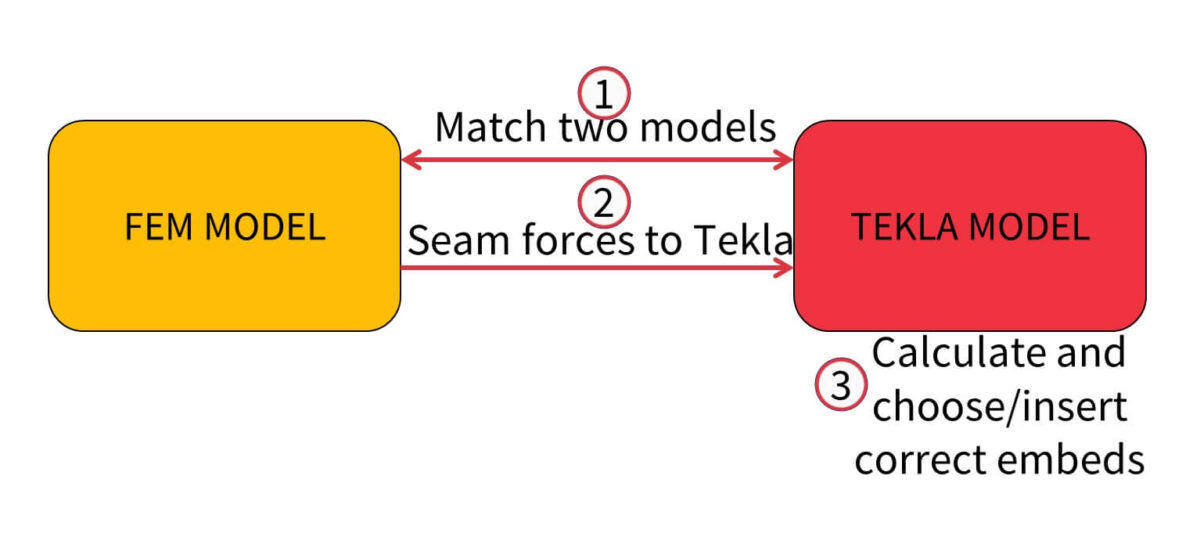
The next thing on our agenda is vertical seams for precast panels. The interesting thing here is that we have to join it together with a calculation model. With that, we are matching the calculation model with the Tekla model; we export the forces in the seams from the calculation model; and then insert necessary embeds in the Tekla model. We can do this in one fell swoop for roughly 80% of any given model.
“We are currently looking at each type of action that you need to perform on an element, for example, insert anchors, insert reinforcements, insert perimeter reinforcements, and so on, and creating actions for all of them so that we can do these actions for the whole model at once.”
What calculation software do you use, and how is the connection between them and Tekla out of the box, and have you developed anything to improve on that?
Jānis: We use 2 main calculation software – Dlubal RFM, and StruSoft FEM-Design. I think the ability to convert from a Tekla model to Dlubal RFM is good enough out of the box, provided you already have existing guidelines on how the Tekla model needs to be created. However, the need for minor adjustments means that out of the box, the connection between these two softwares cannot be seen as a “live link”. After converting Tekla model to the calculation model, we resume working in both platforms separately. If there are any minor changes in the Tekla model, we add them as well to the Dlubal RFEM model.
What we’ve done – as an additional tool – is we have an application that compares both models and tells the user whether or not they are the same, since it’s possible you might have made some minor adjustments in Tekla that you did not apply in the other. It’s a huge help.
Your Tekla dev team has been busy! How big is the team, and what is their main focus?
Artis: We don’t have a simple separation between R&D and dev team; what we do have is at any given time is between 20 and 30 people working in R&D behind ~200 engineers. This is because the development of an application is the last step. For development, we have 3 or 4 people full time, but all the other people are working with the R&D stuff, with the components, with Grasshopper and so on. Important is to figure out where engineers are struggling, spending too much time on manual work and how can we bring up our efficiency. Only once we have figured it out, made the plan and all the preparations and sure everything is in a final state, etc, does it become a new spec for the OpenAPI application development team.
How do you approach the task of new developments?
Artis: I would separate two main themes for development. We have operational development which is focused on how we can optimize daily tasks; so for example, how can we do the things we are doing even better, faster, more accurately, and so on. The other is high-level R&D, where we look at the specific improvements and high-level projects for the future. This team is smaller than the other one. An example of what this team does could be, around 5 years ago, they were playing around with Grasshopper, and as a result today, Grasshopper is a regular part of our processes.
As far as development planning is concerned, it’s an agile process. Obviously, you cannot do this work without engineering knowledge, and finding a dev with an engineering background or qualification is quite difficult, so instead we have a team of both engineers and developers, and they work together closely to achieve the desired outcomes.
Regarding the smaller R&D team; can you elaborate on anything they are working on?
Artis: One of the proof-of-concepts they are working on at the moment is machine learning – essentially, can we, and if so, how can we use it in our industry? At this stage, the answer is not clear, because our industry is naturally very precise, and we’re still looking for various applications of the technology that has a satisfactory degree of accuracy.
They also work a lot on integrations; mainly with the facade unit, as that unit is a lot newer and there is more work to be done and gains to be attained.
Jānis: I would say that right now, the simplest and yet most complex thing we are working on is holes for the facade (aluminium profiles). We have these very detailed aluminium facades in Tekla; a complex model with roughly a million parts, and what we are trying to work on is how can we – with the push of a button – get the profile from Tekla to C&C. Currently, there is a problem around how to get all these holes in Tekla, and it’s a question of do we even want all of these holes in Tekla. At the moment there is an export problem, so we don’t currently create the holes in Tekla, but with each year, we get closer to the point where Tekla will be capable of handling these additional holes (around 20 per profile) and also export them. This is a big problem to solve for engineers, because if changes are made to the model, it can result in changes needing to be applied to millions of holes! So we need to ensure they are correct by means of a tool – it’s impossible to check them all manually.
How do you share new tools once they are created? How do you decide which tools should be used?
Artis: We have a Quality Control system and documentation. Engineers can access it any time and get the latest versions of anything we’ve documented.
Regarding tools, we have an internal synchronization system, whereby we upload every tool, template, and so on that should be included in an engineering toolset – not only for Tekla. In that system, we organize it clearly, by project, by company, and so on. From there you can assign these toolsets for a particular team, and thusengineers on each team have only the data they actually need on their local machine.
Jānis: This “internal warehouse” ensures that if an expert-level user generates a template, attribute file, etc, in around 10 minutes, everybody connected to that project or team will have it on their machine as well.
But on to the part about communicating the existence of these files. We actually use analytics to get an idea of how many people are using different tools. For instance, we know how many drafters we have; we know that we have a very good function for them; but if we see that fewer users of that function than we have drafters, then we need to send out a notification to them all so that they know that it’s there to be used.
Previously, we also tracked clicks in Tekla and we could record how long it takes to create an element drawing. From all that data, we could see if there were any discrepancies; for example, we can determine why some users are much faster than others at completing certain tasks. It turns out that in many cases, the faster user is using functions and tools that the slower users were not aware of, and that makes it easy to improve efficiency.
Finally, about a year ago we simply started interviewing people. We had records of all the tools and functionality we had by role (eg. engineers, drafters, etc), and we basically asked if they were aware of each one, whether they use it, or if it wasn’t applicable to them. There we get information about what tools the engineers are aware of and they will get hints about what to explore more.
If an expert-level user generates a template, attribute file, etc, in around 10 minutes everybody connected to that project or team will have it on their machine as well.
What are some of the “rookie mistakes” you notice are common among users? How to avoid these mistakes?
Jānis: In my experience, one of the most common rookie mistakes is that when a new user starts, they accidentally delete something! That can be very costly so you would want to put measures in place to help avoid this.
Overall, regarding rookie mistakes, one of the applications we have developed is called “Model checker”.
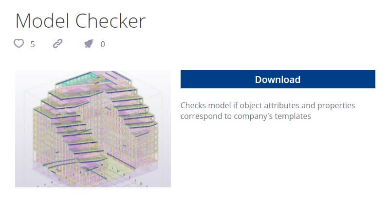
It assists in checking an element for things like whether you have used the correct country grades, types; is the element acceptable for manufacturing, and so on. This application runs during the night and literally goes through everything according to a pre-set set of rules. This way we eliminate most of the mistakes that commonly are made by newer users.
Continuing on this quality theme, though; we also make sure that everything is always checked by at least one fresh set of eyes. This is quite a rigorous process involving checklists, which means that the task is always treated as a serious one.
Any tips on getting the best performance from Tekla?
Jānis: First of all, I would recommend learning all of the manual Tekla functions. Master them. Once you’ve done that, you can make a big leap forward in productivity by learning about Parametric Custom Components. Finally, start working with Grasshopper, or another (e.g. C#) scripting method. That makes parametric components even more efficient because you can automate processes with them that you would otherwise need to do manually. This will literally save you hundreds of hours.
How do you decide when to perform tasks manually, versus developing something to automate the process?
Jānis: On one hand, we have a lot of statistics, meaning we know how engineers are spending their time. This allows us to evaluate how much time we could save by creating tools. But in our case, we are also fortunate that management encourages us to pursue these gains. We simply need to make sure we compare how long it would take to develop a tool versus how much time it will save in the long run.
For instance, with Grasshopper, it’s very easy to develop these concepts. And when it comes to completely automating a modelling process, it’s just a no-brainer; we commit to developing tools for those things.
Then of course there are the developments that empower users to do things that previously weren’t possible.
Artis: To go a bit further on developing tools, think of the black box / white box concept. With one huge black box tool, it completes many tasks for you but you have no idea how it gets done.
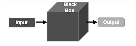
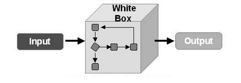
With more smaller white boxes, you’re able to see and understand how everything gets done. We prefer the white box approach, because with transparency and ability to cross-check things comes trust in the process and the maintenance is much easier. It cannot be understated how important that is.
How would you like to see the level of tech outside of engineers offices catch up to what happens in the offices over the coming years?
Jānis: I would really like to see improvements with augmented reality precision level. It would be fantastic for quality checking to be able to get a virtual element or even the whole building anywhere you want.
Artis: I would really like to see an uptake in the use of Tekla model information. We have great 3D representations of a project with a lot of information, but so many factories and construction sites are still using only 2D drawings and a lot of BIM model benefits are not used.
In Tekla Podcast #5 episode we will have guests from ALTO 4.0 who has developed coworking with UPB an ERP system Alto ERP and there you can see how they are using Tekla model information in their ERP system and in the whole project work-flow.
Any last comments or advice?
Jānis: Never stop improving yourself! You should always have some drive in you to learn something new. It’s akin to investing in yourself and your future.
Artis: I would say that also, we need to improve our digital level. Our industry is kind of lagging behind, and I believe we need to introduce more digital solutions, particularly around working with data. We need to keep working to raise the bar in terms of digitalization; doing so will afford us new opportunities, and everyone will benefit from it.
AUTHOR
FIND THIS USEFUL? SHARE IT!
[Sassy_Social_Share_Pro]
YOU MIGHT ALSO LIKE

Today’s Tekla podcast guest is Juha Nieminen, from none other than Trimble – and no doubt virtually all of you know Trimble! He works in the Finnish HQ as a service manager providing support and also running webinars.
Juha is a pretty unique guy in that he rides his bike to the office – all year round – in Finland 😲 and of course he has lots of experience with our Tekla problems. In this interview, we will share ideas on how to solve and avoid Tekla problems. In the second part, Juha will not hold back on sharing his tips on how to maximize Tekla efficiency and minimize errors.
Watch the whole interview video from here:
ARVE error: Mode: lightbox not available (ARVE Pro not active?), switching to normal mode
or listen it in audio format here:

Don’t have time to watch the whole pod? Skim the questions and answers summary in a written format below! 👇
When was Tekla first created? And, what does the word “Tekla” mean?
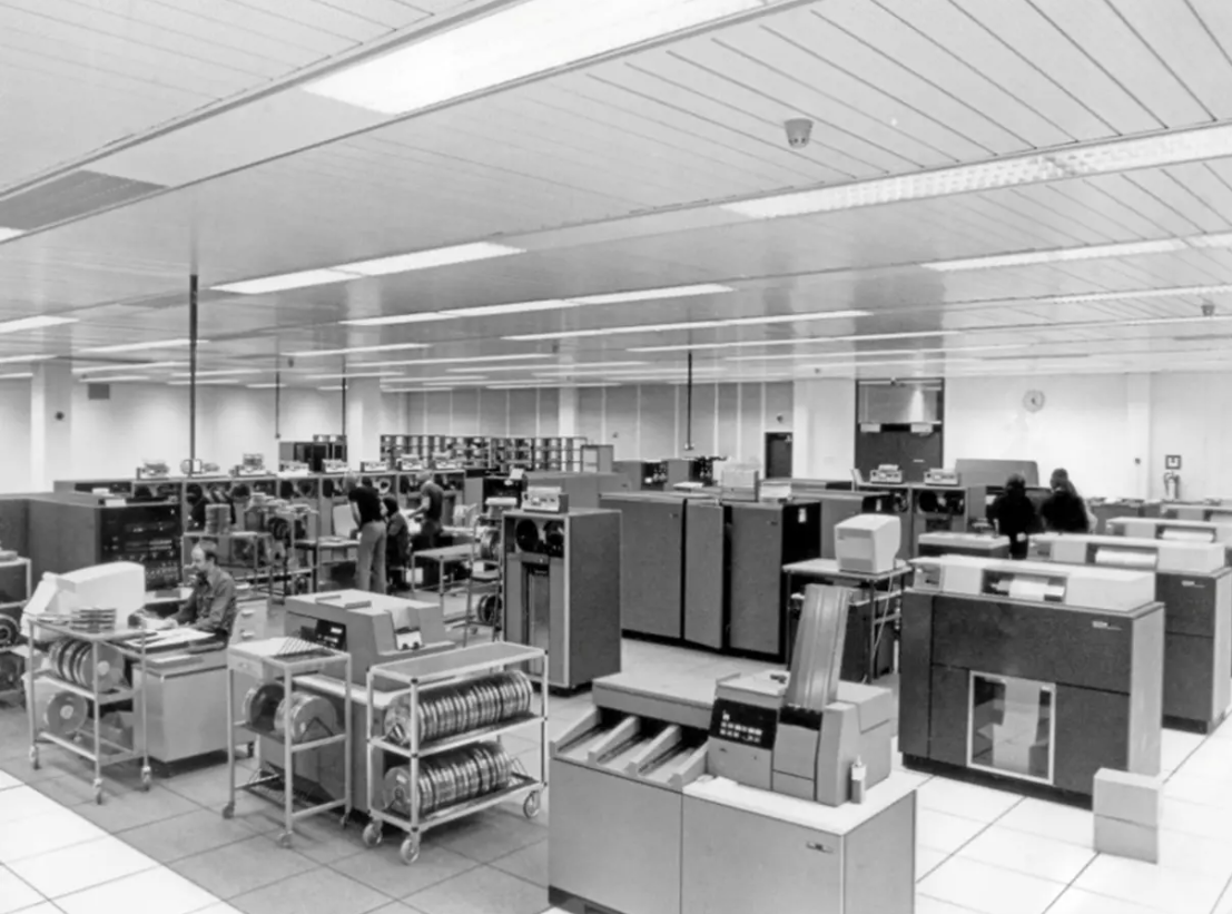
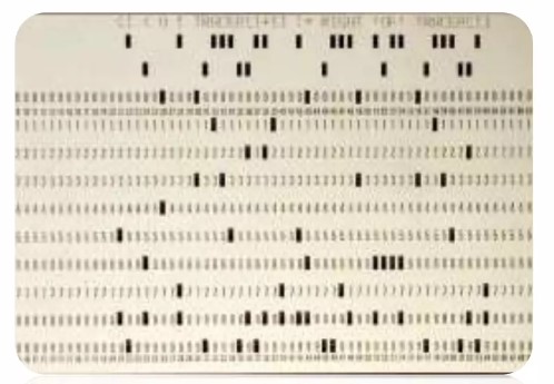
The company was actually founded way back in 1966 when computers were still using punchcards!
The word “Tekla” is actually quite an uncommon Finnish women’s name. There is a particular Finnish woman (https://en.wikipedia.org/wiki/Tekla_Hultin) who was named Tekla who is quite well-known for her struggle for men and women to have equal rights – however, I don’t think that’s the true origin of the name. Officially, the name is a combination taken from Finnish words Teknillinen Laskenta , which translates to Technical Calculation in English.
Tell us about how you ended up joining the company, and a bit about your team.
Well, it’s now been more than 13 years. Originally I saw a good-looking ad at some kind of (job) fair. They were looking for engineers for the support team, and, somehow they chose me 😊
As service manager, I’ve actually been running the team for quite a few years. The scope of software the team supports has grown quite a lot as well. Back when I joined, it was just Tekla Structures; now it includes Tekla Structural Designer, Trimble Connect, Tekla Tedds, Trible Vico, and most recently, Tekla PowerFab.
What do you feel are the most common Tekla problems?
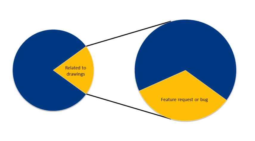
On the general level, roughly every fifth support request relates to drawings, and from those requests, there wasn’t any clear stand-out topic; things were more or less evenly distributed. Having said that, around one third of those requests were either feature requests, or things we ended up reporting as bugs.
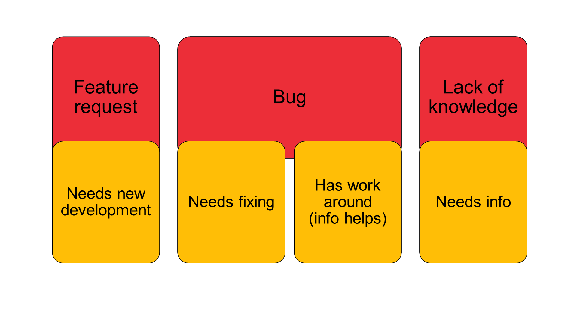
What would be the breakdown between feature requests, bugs, and a lack of user knowledge?
Interestingly, bugs without a workaround and feature requests would make up only around 5% of all cases. The rest goes to the situation where a user is trying to do something in the way they feel it should be done, but we end up providing them with the correct instructions or help them with a workaround for trickier situations. And many times, we simply provide more information in the form of articles or recognize that the user has too great a knowledge gap and so we recommend they seek additional training.
I understand that in Trimble there are people who do development based on client feedback and others who are about future product development?
That’s true; the support teams and the area offices take feedback for the future developments and then there is a development team with their heads in the clouds ☁️😄☁️ These ones are not looking ahead not to tomorrow or the day after, but a year or more into the future with their thoughts about where the software should go!
I have some slides prepared today about what users can do when they have errors; let’s go through them and you can give me your thoughts as well!
Search for the error code on Google
Google, of course, is always worth checking, as there is a good chance somebody else has already encountered the error. In fact, some of our staff will do that in the case of a new error, just in case they find a user who already encountered it and found the solution or even a workaround.
It’s just important to prioritize the official advice given from Tekla Support over suggestions posted elsewhere. You can get Tekla official support from here https://support.tekla.com/
Finding the source of error
This slide helps to identify where the actual source of the fault lies:
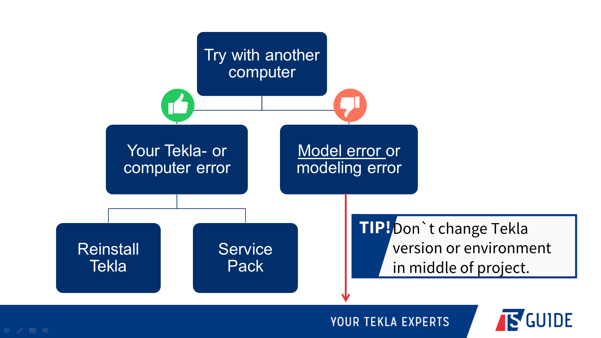
The first thing to do is check and see if the same issue exists when using a different computer – and even better if that other computer was outside your office, if possible.
If you can’t reproduce the error on other computers, then it’s a decent chance that the problem is unique to your computer. In that case, the best thing to do would be to re-install Tekla or apply the latest service pack.
We don`t recommend changing Tekla main version in the middle of a project. But if you need to do it, in a very long project, read this article before doing it https://teklastructures.support.tekla.com/support-articles/upgrading-shared-model-new-tekla-structures-version
In the case where a model or modeling error
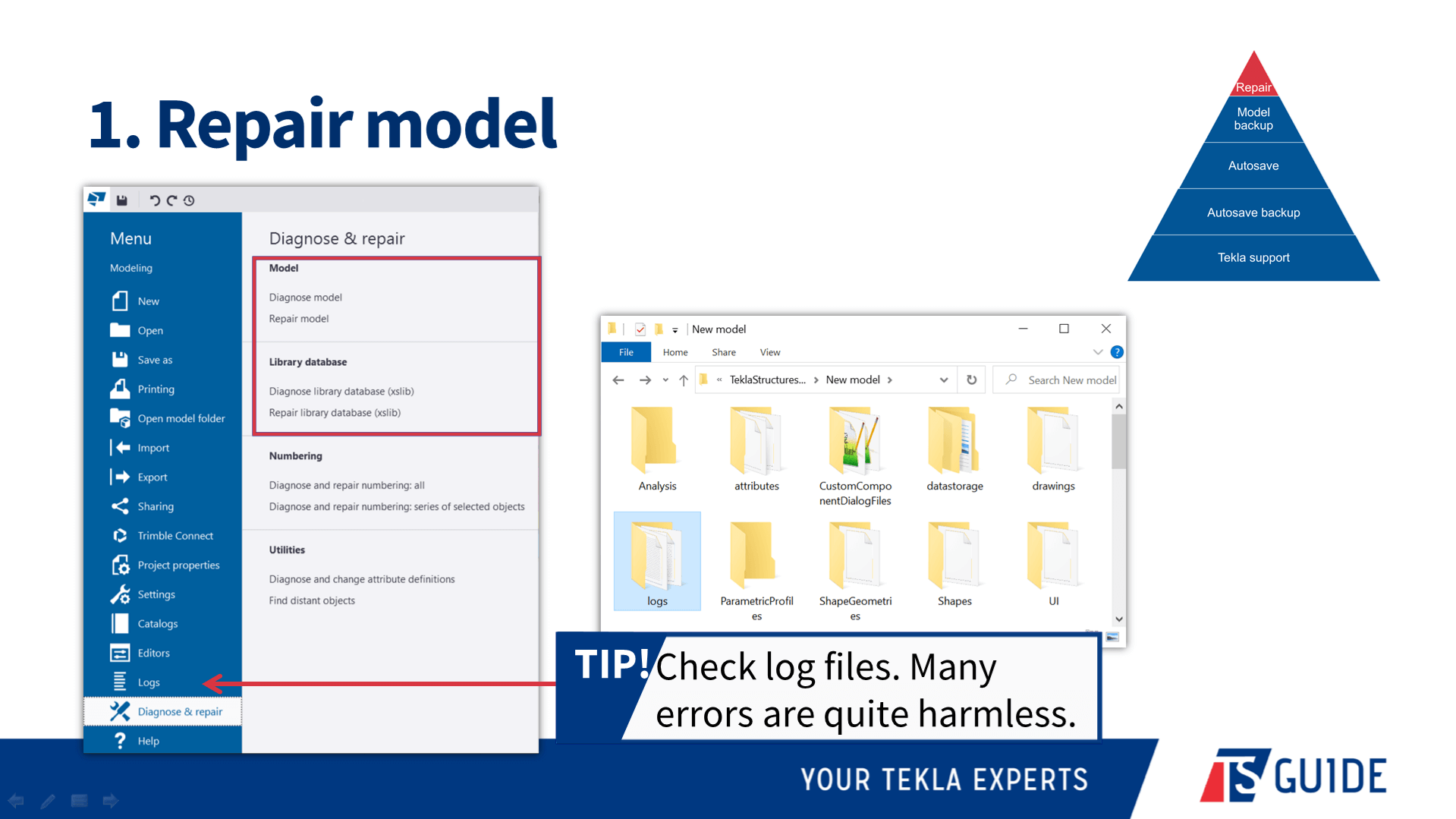
These are the five steps that I follow when trying to resolve model or modeling errors.
- Model repairs: If you can still open the model, running a repair is the fastest and easiest way to solve (some) problems. And of course, restart your Tekla. We recommend to run “Model Repair” daily. Make it as a good habit.
- Model backup: Tekla is continually making backups, and this means you can take the step of restoring the most recent backup. You just have to rename *.db.bak to *.db file. Just in case keep your previous *.db files somewhere safe.
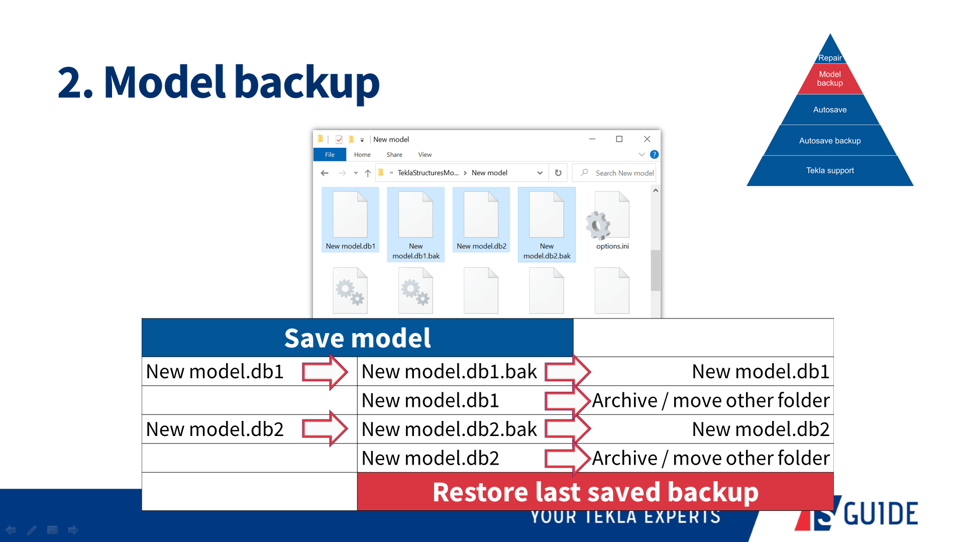
Advanced option XS_STORE_MULTIPLE_BAK_FILES enables creating more than one bakup file. In this case you need to delete manually old bak files, when there are too many of them.Advanced option XS_MODEL_BACKUP_DIRECTORY is for controlling the location where bak files are stored.
- Autosave: If the model will not open, autosave can come in handy to re-open the most recent working version.
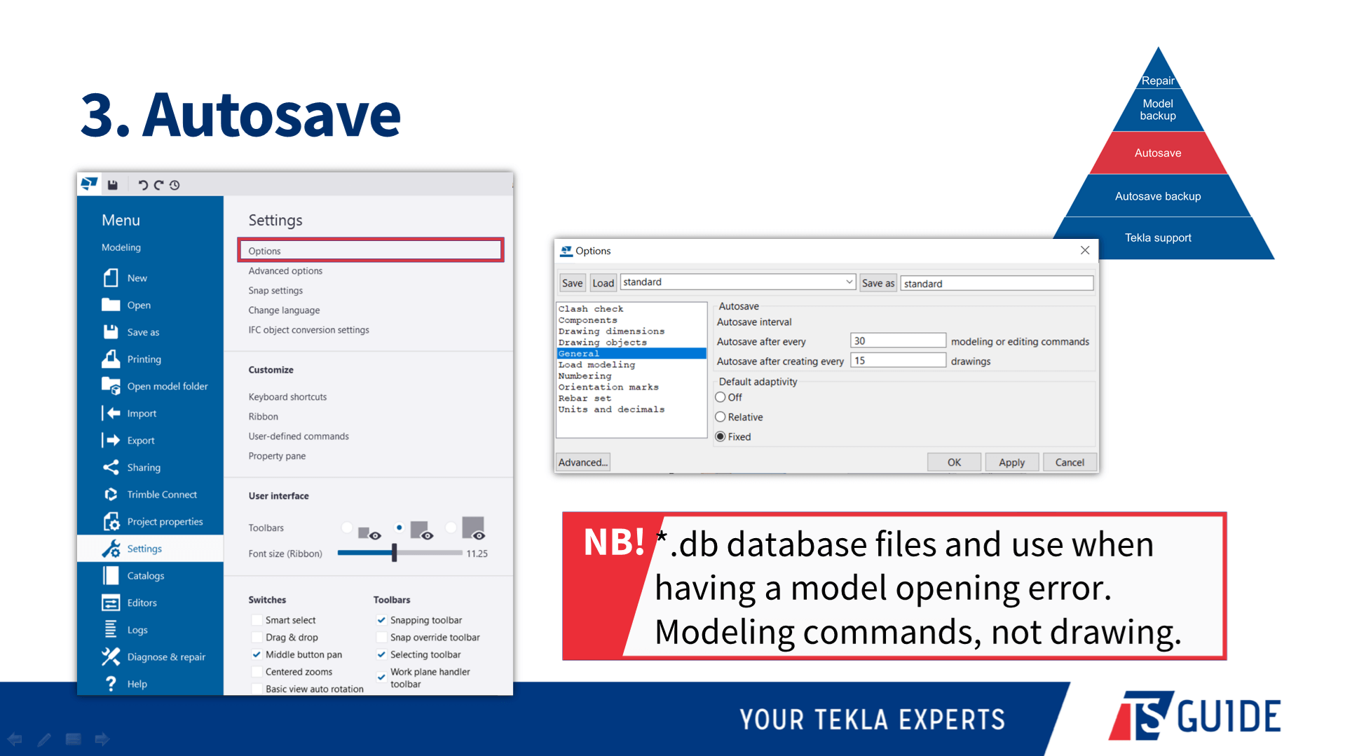
Remember that Tekla does autosave after x number of different modeling commands and it`s not counting the work you are doing on drawing space. - Autosave backup: There are a few different ways you can automatically make server backups to backup server or to the cloud – redundancy is a powerful ally to have!
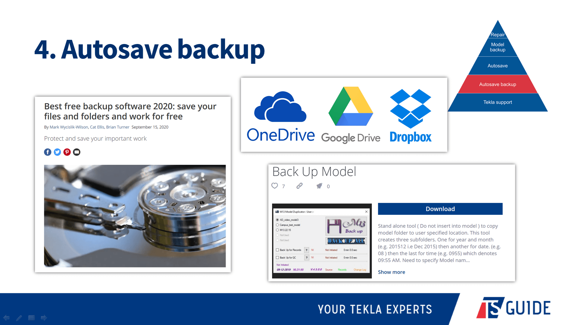
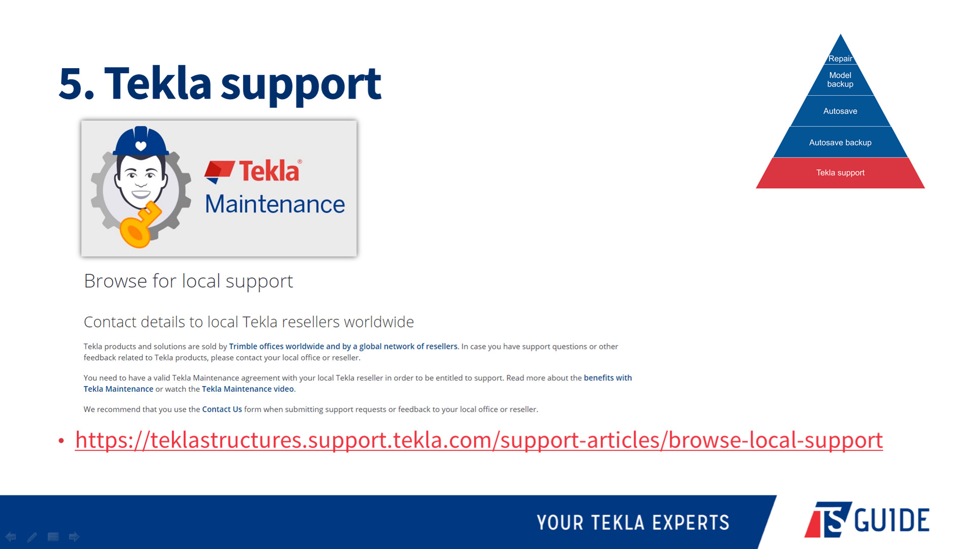
- Tekla support: Now that you have all these options available to you, in many circumstances you can resolve the problem yourself. But, if you don’t manage to, at that point your should get in touch with the support team. Browse for your local support here https://teklastructures.support.tekla.com/support-articles/browse-local-support
Make sure that your subcontractors are not using pirate version of Tekla. Tekla support doesn`t like these models too much.
When contacting support, what information should customers provide for a faster resolution?
This information would be best to include:
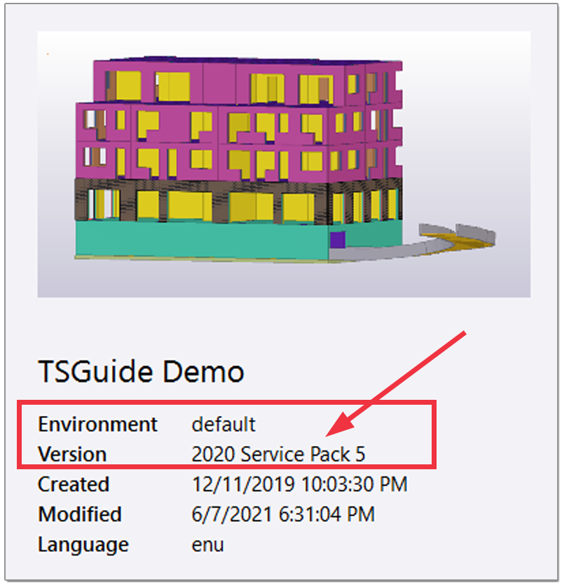
✔️ Tekla version
✔️ Service Pack number
✔️ Environment type
✔️ Configuration / license
✔️ Single, multi-user, or model sharing setup
✔️ Your computer’s operating system (Windows version)
✔️ Tekla model files (where appropriate), support tool in Tekla zips it automatically for you
✔️ Description of what happens and what you are expecting
✔️ Screenshots (as attachments, not embedded) 🖼️ or even better – screen recordings 🎞️
Keep your documentation and support requests short and simple!
Any other tips on how to avoid errors?
Firstly, don’t make cuts and fittings align to the object! This error was common for a time but more recently has lessened, but doing this will definitely cause solid errors.
Next, don’t open the model with the wrong environment. Opening a project in an environment that it was not created in can cause errors, for sure.
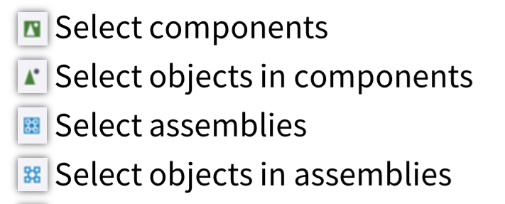
Another thing that will help you day to day is to learn the difference between the selection switches – your life will be a lot easier once you have mastered this!
This is just a good habit to get into – try to remember exactly what you did when an error pops up. Not knowing what your last action was prior to an error occurring makes it more difficult for both you and Tekla support to figure out what went wrong! 🙃
Don’t be afraid to go to forum.tekla.com and ask for assistance. There are expert users from all around the world who might be able to help with your problem, and they enjoy doing so.
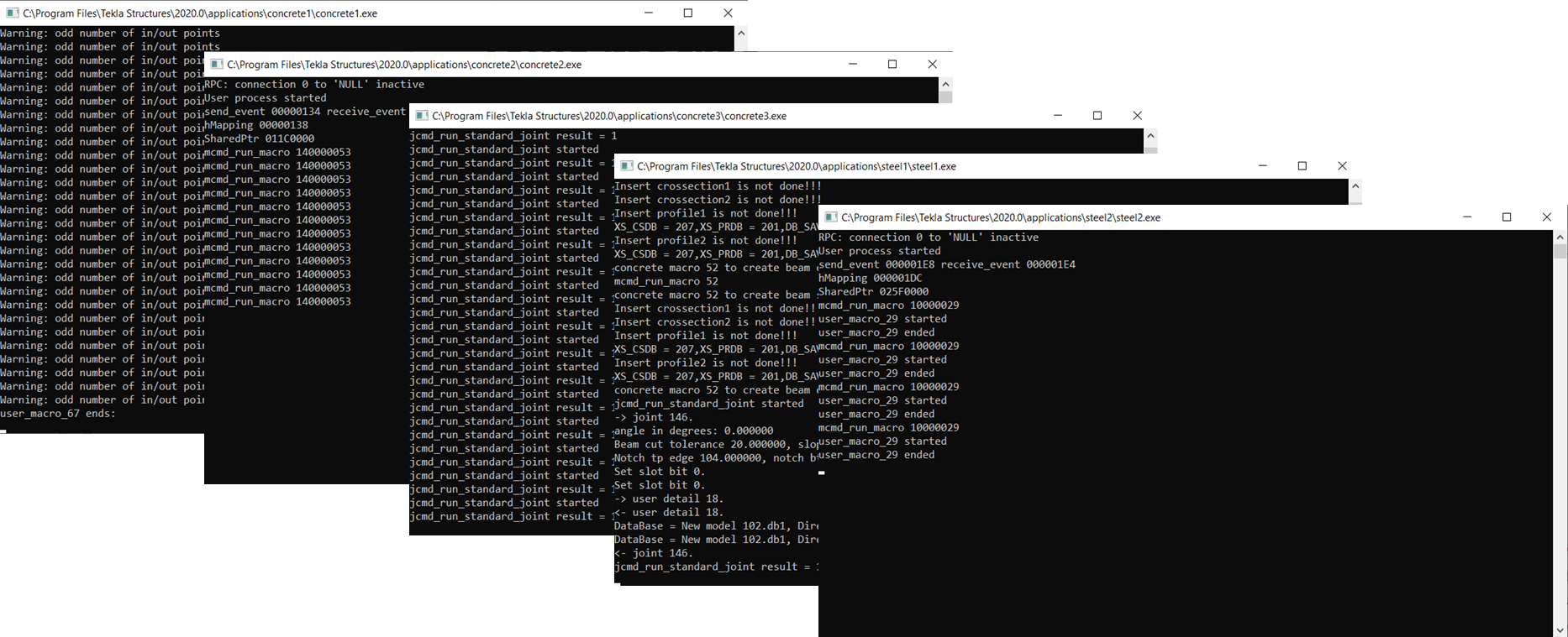
Don`t close Tekla separate macro windows or as I call them “black boxes”
Any tips on hardware setup for running Tekla smoothly?
You can find Tekla official hardware recommendations from here https://teklastructures.support.tekla.com/2021/en/ins_tekla_structures_hardware_recommendations
If there is one thing I would say, it is that when you look at the minimum hardware requirements – make sure that the computer you want to run Tekla on has MORE than the minimum requirements.
You don’t necessarily need to have all of the recommended specs, but just scraping in with a computer that has the minimum specs won’t be a good experience, and gets worse as your models or projects increase in complexity.
Also, make sure that you read and understand this article https://support.tekla.com/article/tekla-structures-and-central-processing-unit-cpu-usage, before choosing a new computer. It will help you.
Plus, you can ask to run Tekla Structures graphics hardware test to find out how suitable your chosen computer is for working with Tekla. You can get it from Tekla Warehouse https://warehouse.tekla.com/#/catalog/details/ucac83627-77c6-4e39-a67e-400379dca22a
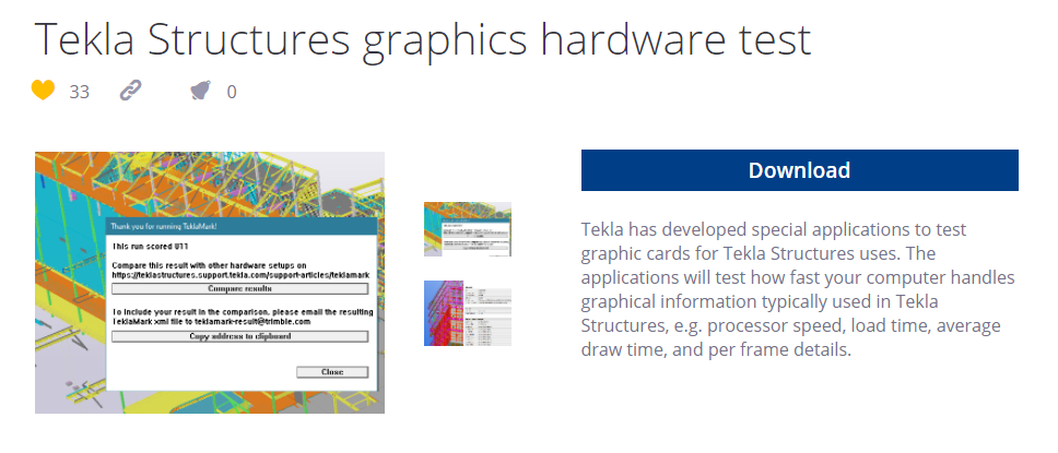
One other thing that does affect some users is that you should make sure that Windows itself is up to date. Sometimes a computer is set to not automatically update, and this too can be the cause of some issues.
What are some of the “rookie mistakes” you notice are common among users? How to avoid these mistakes?
👉 The first one, which was already mentioned but I will do so again now because of its importance – and that is to make sure you open a project in the correct environment.
💡 Remember that there are different tools for creating steel and concrete objects – try not to mix them up!
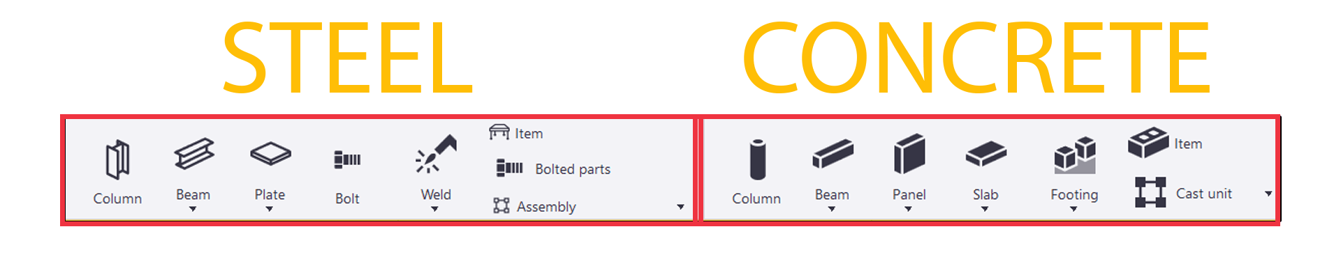
👉 Be careful when you’re picking points. You have the ability to create clip lines and plane views, but if you aren’t very experienced, choosing the wrong one can lead to trouble down the path, so pay particular attention to that. Use object edges and corners; avoid using surfaces in transparent view mode.
💡 Perhaps not so much a rookie mistake, but making sure that your common modeling rules in any project are clearly defined. These affect numbering, and you need to have those settings properly in line.
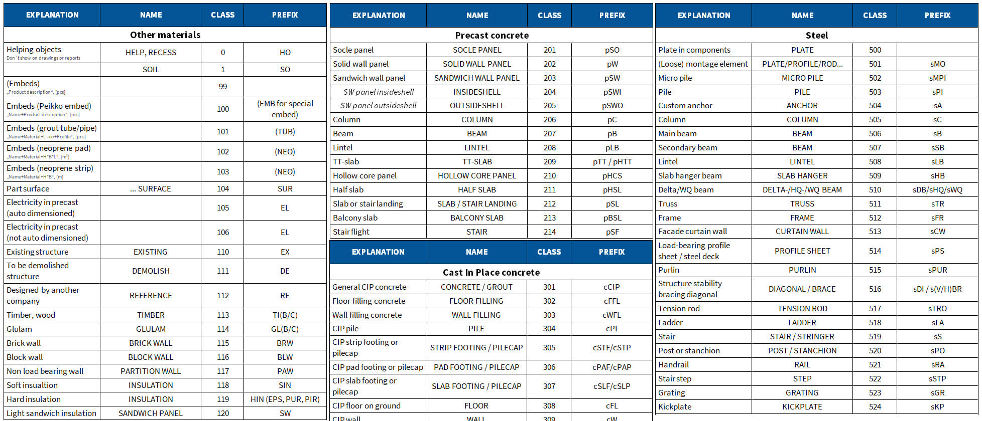
💡 Location in the model should be coordinated near to orego 0, 0, . Use Base Point feature if needed.
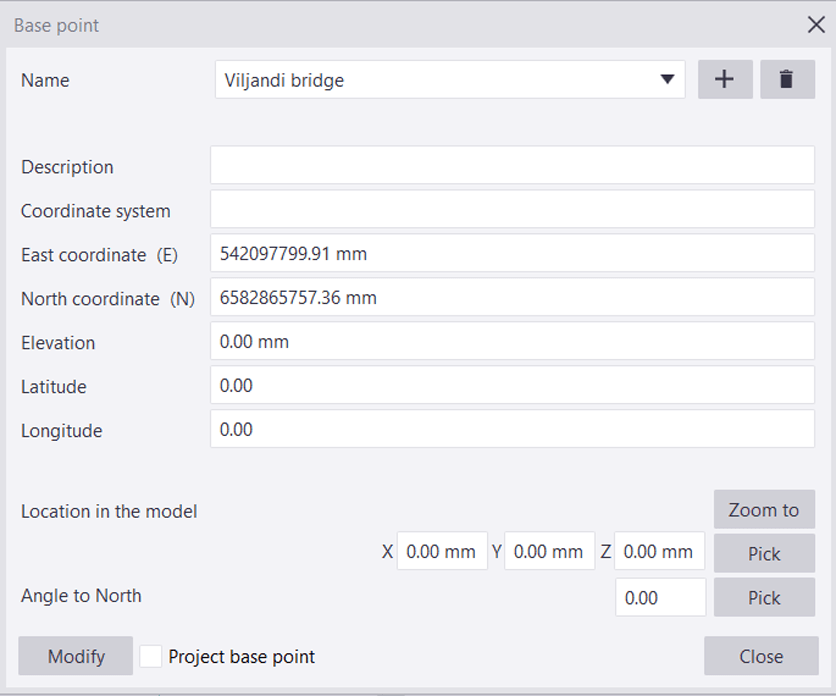
👉 In multi-user projects, divide the project between users and make sure that they will not modify the same objects at the same time.
👉 Make sure you know how to model manually, but don’t forget to use components and save the settings for the next times. It will raise your modeling speed and reduce typing mistakes.
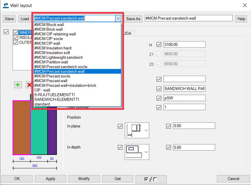
👉 It doesn’t matter how high your skill level is – never be afraid to ask for help; you might avoid some big issues later! Help others if you can. Sharing your knowledge will help other users improve, and it’s karma that will pay itself back in time.
👉 Get training. Whether it’s in person or online, whether paid or free, getting yourself further training is going to improve your understanding of the system and expand your skills, ultimately meaning your projects will be more accurate and have fewer errors, and you can work on more and more complex things. Training is essential!
Contact us here https://www.tsguide.eu/tsguide-contact/ to get personal training or read our very good article (with links) where else you can start learning Tekla https://www.tsguide.eu/11-ways-for-beginners-to-learn-tekla-structures/.

👉Use Tekla locking possibilities, e.g grids, references, objects and drawings.
Any tips on getting the best performance from Tekla?
First off, and easiest, the performance of Tekla can be increased by maintaining a smaller model size (eg. create separate buildings in separate Tekla models and don’t model every brick if you really don’t need it) and having fewer visible objects (eg. hide reinforcement when you don’t need them and show only the area of the building that you are working on, using Work Area and View Depth). Both of these tips work in model and drawings.
In your modeling, use reasonable precision, for example with round shapes. In Tekla, there are no true ’round’ objects; they are always built using smaller and smaller segments. The smaller the segments, the slower they will be rendered, so make sure you don’t go overboard with the segments if it won’t affect the accuracy of your design. Read more from this article – https://teklastructures.support.tekla.com/support-articles/roundness-objects-displayed-tekla-structures
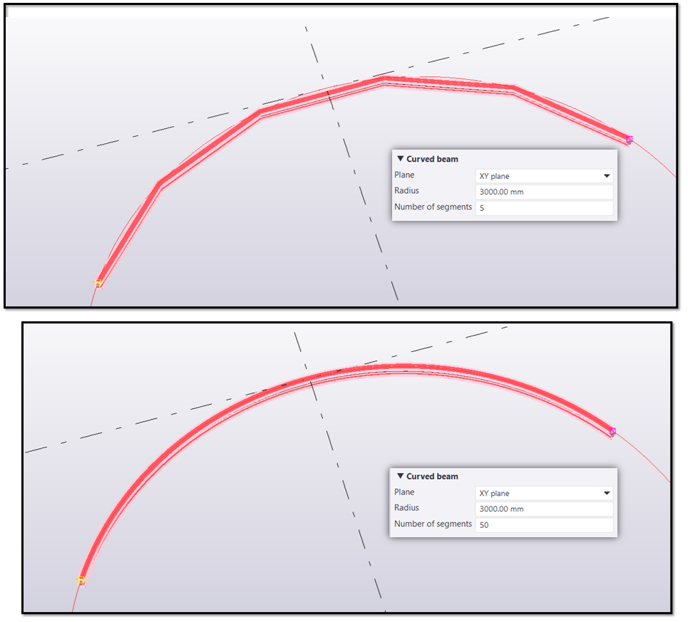
In Tekla version 2020 and newer, don’t use “Use legacy rendering” = open GL rendering mode. It means that your Tekla will use DirectX rendering. It has been improved a lot.
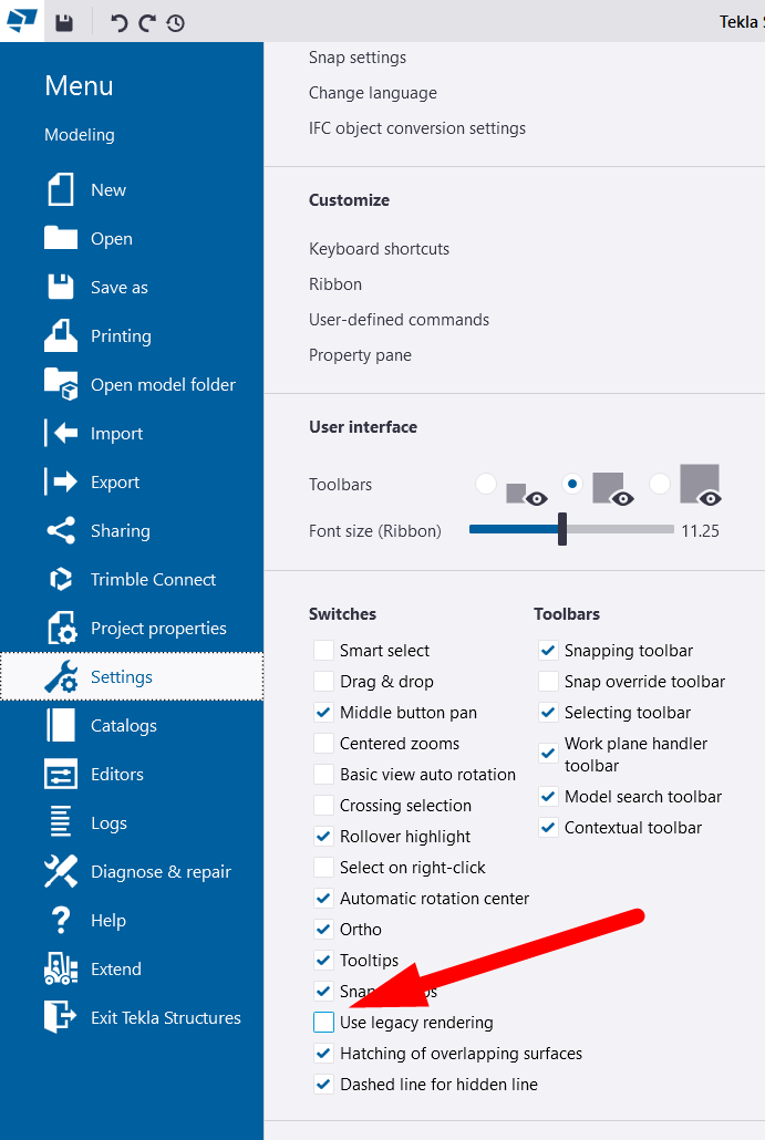
Use drawing snapshots, check the whole drawing, make notes, and then do all changes in the model in one go; this will be faster than fixing them one at a time as you find things you need to change.
An easy way to streamline your work is to remember that create CU drawings for smaller elements and GA drawings for large areas.
Use keyboard shortcuts. There are cheat sheets available, but you can define your own favorites.

On drawings, your zooming and panning performance can improve if you will use XS_USE_SMART_PAN from advanced options. Read about it more from here – https://support.tekla.com/doc/tekla-structures/2021/xs_use_smart_pan
In fact, if you go to our support and search for performance, you’ll find a lot of articles on this and they are constantly updated. These are only some of the articles that we recommend to read:
- https://teklastructures.support.tekla.com/support-articles/general-tips-faster-model-performance
- https://teklastructures.support.tekla.com/2020/en/sys_modeling_tips_for_large_models
- https://teklastructures.support.tekla.com/support-articles/tekla-structures-performance-issues
- https://teklastructures.support.tekla.com/support-articles/how-check-graphics-card-used-tekla-structures
- https://teklastructures.support.tekla.com/support-articles/selecting-correct-graphics-card-tekla-structures-windows
- https://teklastructures.support.tekla.com/support-articles/tips-speeding-organizer
Finally, the question I ask of all guests: What do you see in the future of BIM?
While I’m not an oracle, I certainly believe that AI and machine learning will become more and more of an important part of the industry. I believe that AI will ensure engineers will need to do less repetitive manual work.
Hopefully, this AI and machine learning becomes more prominent in the field and on sites; this would mean huge savings from streamlining work and realizing real productivity gains.
Thanks Juha! Any last comments or advice?
Always keep a curious mind! And try to be humble; while you might have a certain amount of knowledge today, always remember that there will always be room for improvement, and try to plan your next steps.
Having an eagerness to learn to bring joy to your work, despite sometimes having heavy workloads. 😊
Go also check our first podcast episode Tekla Podcast #1 – Consolis CES Estonia advanced Tekla system and development.
AUTHOR
FIND THIS USEFUL? SHARE IT!
[Sassy_Social_Share_Pro]
YOU MIGHT ALSO LIKE
Consolis is a European leading industrial group providing sustainable and smart precast concrete structures. They are specialized in the design and manufacture of high-performance precast concrete products.
Morten Kaasik has 5+ years of experience as a structural engineer with Tekla Structures and now he is Design Modelling Tools / BI Development Manager at Consolis CES Estonia.
Start watching the interview video here:
ARVE error: Mode: lightbox not available (ARVE Pro not active?), switching to normal mode
or listen it in audio format here:
Don’t have time to watch the whole pod? Skim the questions and answers summary in written format below! 👇
How did it go in the beginning with using Tekla in your company? What advice would you give to a company considering implementing it?
For us, it was probably a bit simpler than for most. The Swedish side of the business had already built their own Tekla Environment – settings, drawing templates, and so on. The big obstacle was that everything was in Swedish. Having said that, the technical vocab was there as we had been working with Swedish templates in Autocad, so it wasn’t a huge obstacle.
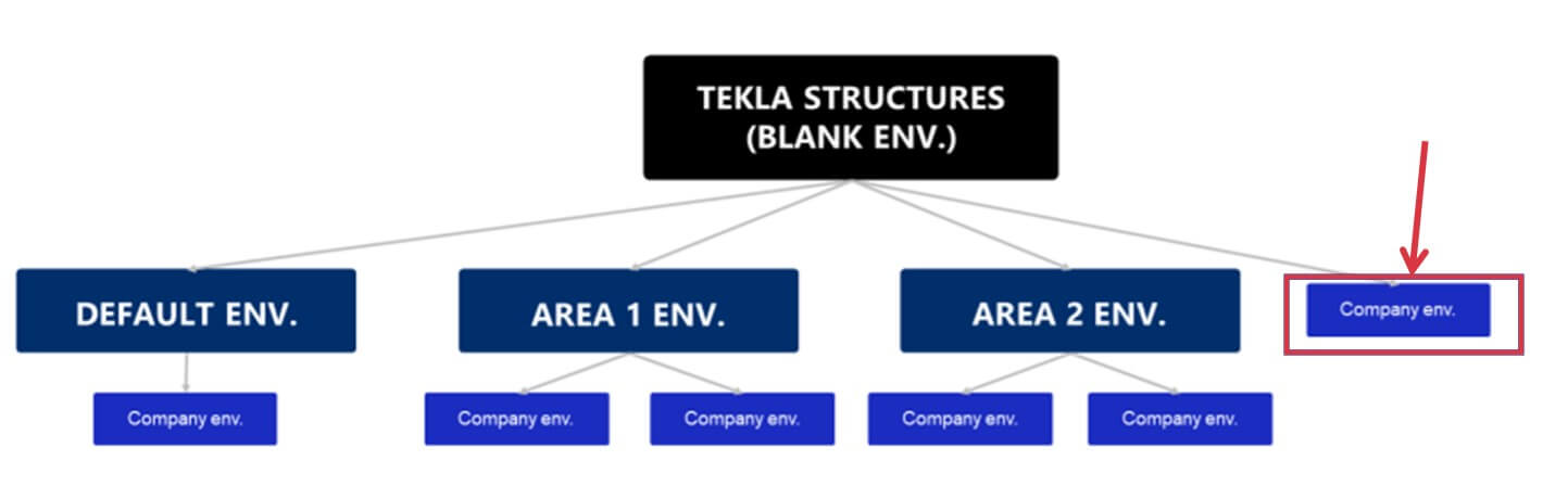
The biggest challenge was that I was the only one who had used Tekla before, as I had been involved in some other projects on Consolis using Tekla, so I knew some basics like how to reinforce elements and how to create drawings, but I was still mostly learning on the go. I think we still look back on this project and we believe that if we were going to do this project again, we wouldn’t do things any differently because we did not have the knowledge to realize there was a different way to do things!
Of course, in hindsight it’s easier to say things like yes, we would have automated things like drawings and how to use more components, but still we were mostly learning as we went.
During this first project I actually started creating custom components; I had no experience with that but it was about looking really critically at what you were doing. For example, if I had 500 wall elements, and wanted to add a very specific detail to all of them, I started to think “Hey maybe there is a better way?”. For example, in Autocad we have blocks. So I Googled a bit and saw that you could create custom components. I must admit my first custom component was quite ugly! But it did the job.
But my advice to anyone who starts to implement Tekla at their company would be to do planning before anything else – which templates you will be using, which environment you will be using. And if you have some very specific solutions you need to create, then definitely check the Tekla Warehouse (warehouse.tekla.com) because there might be some tools available that could help you. if not, then definitely look into the Tekla forums (forum.tekla.com) where there is a lot of advice and assistance to help make your work better. Look very critically – don’t use Tekla as you used Autocad; make sure you unleash the potential of Tekla.
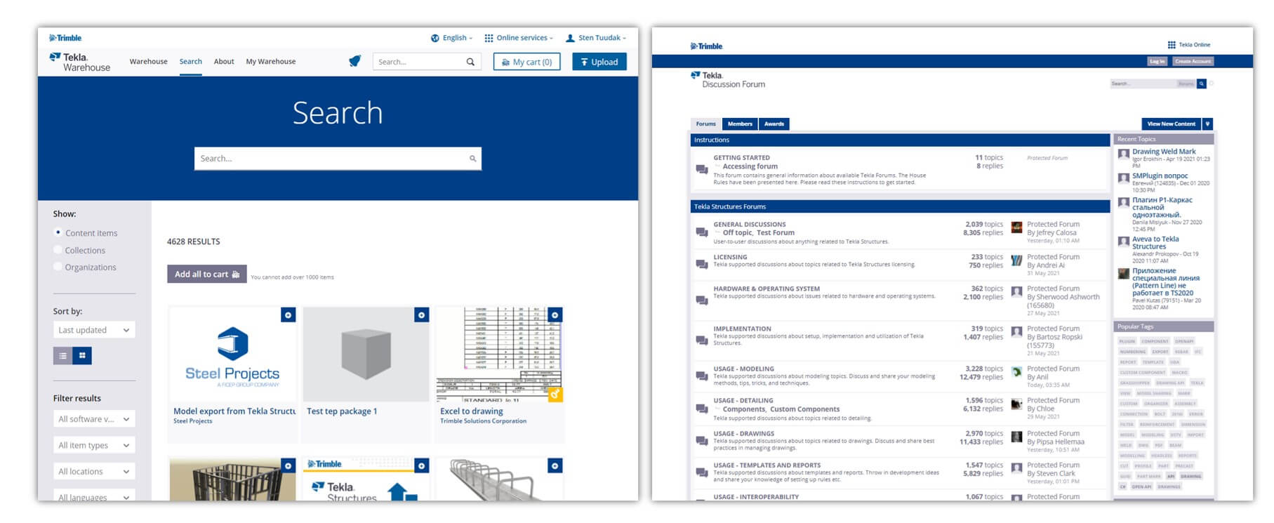
What’s the most important thing when you want to work with Tekla? Development? Training? Hiring expensive engineers? Internal training?
The way I look at it is that Tekla is a huge toolbox. One of the most important things to do is identify the needs of your company and the challenges you need to solve, and then from all the tools in this huge toolbox, identify the main ones that you should be using. Next, create simple procedures that all designers can follow – the larger your company, the more important this is to help ensure consistency, accuracy, and efficiency.
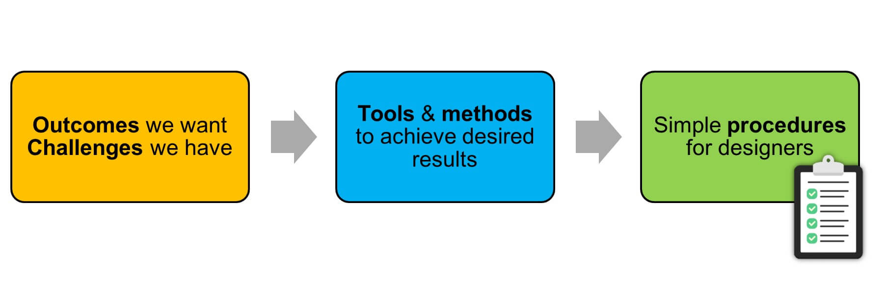
What about developing custom components versus just doing them yourself? How to judge the ROI?
Simple components can yield tremendous benefits via quick wins.An example would be that doing the drawing automation would take, say, 24 hours to develop. But if my project hours are 1000 hours, and if doing this 24 hours meant I would save 100 hours in design work, then it was a no-brainer. But if it’s not so clear that it’s a benefit in the short term, then try to assess if it could apply to more than 1 project, eg. If it’s a tool or a setting that I can use in all my design projects, then ultimately it would be worth doing.
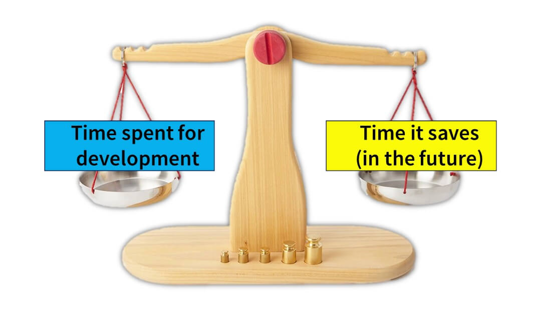
You have around 45 engineers in Estonia. If one creates a great tool or setting, for example, how are you ensuring that everyone can have access to it so that all can benefit?
There are a few different options for us. As mentioned earlier, we work across the Nordics and Baltics. If we take the biggest of those – the Swedish office – they have more than 100 designers. But CES is also in Poland and Romania, so almost 200 all up which means if we create some smart tools, we want to make sure all designers can access them. We’re putting a lot of effort into making sure that everyone is using the same tools – don’t reinvent the wheel!
To share these tools and even some settings, we use Tekla’s firm folder capability. This is controlled by the main office in Sweden. However, in addition to that, we also utilize the project folder functionality, and that’s where we share the assets we create with all the Estonian, Polish, and Romanian colleagues.
We try to share as much information as possible in our company’s communications channels. This year, we started tackling the challenge of how we could check and verify that people are using these tools – but that’s another topic!
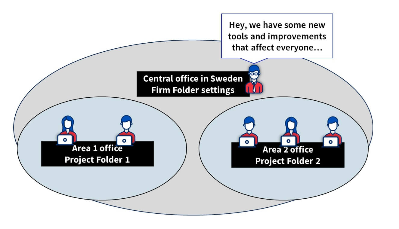
I assume your developments are all in English, given that you work directly with multiple countries. How do you manage that?
For us, it’s a transition period, because Consolis has historically acquired companies from many different countries, which means that in each one there are a lot of older tools, which are naturally in the local language. But now, all new developments are being done in English, which includes the UI, so that anyone from any location can easily benefit from the work of others. Having said that, of course, drawings are produced in the local language.
So you work with many different business units in various locations. What’s the difference between them?
Actually, I think the differences between them all are a lot smaller than people might believe. Of course, there are differences in the solutions made and so on, but the basics are always the same; you need to have a tool for adding lifting elements, you need to have a tool for adding connection items to elements, and so on. Naturally though, there are differences in different regions; our Finnish office might make really standard solutions; mainly for apartment buildings, and usually, the span of the hollow cores is very similar, and the wall elements are really simple. Whereas some of our Swedish business units do more tailored solutions as well.
You mentioned that, for example, different countries have different embeds and connections. How do you approach this? Do you use different firm folders? Project folders? Or different model templates?
That’s actually something we are working hard on now in Consolis. We’re actually creating a common environment now for all Consolis companies. Historically each company has had its own Tekla environment, they have maintained them completely separately with their own firm folder and template settings, and so on.
Now, not everything can be standardised, of course; but the advantage will be that if you have more and more common tools, then you should share these common things. We have a separation of common tools which are the same for all business units, but then each unit has their own folders where they can store their localised templates and own content.
So you said the company is going to have a common environment. What are the benefits the company expects to realize from having it over the standard environment?
I think that it gives us the flexibility to use our own folder structure if there is a particular way you want to have it. But the main benefit really is to ensure that everyone in the company uses the same settings , and if it’s necessary to modify anything at a local level, you still have the flexibility to do so.
How big is CES Estonia? How many BIM managers are there?
Usually, in one business unit, there will be 1 Tekla specialist (or development engineer, however you would like to call it) who maintains the local part of the environment, and also provides support for the users if needed. But since we are a group, we also have someone at the central level to organize all the communications between the business units. So, we have development engineers at the group level, and even have engineers dedicated to developing tools at the group level.
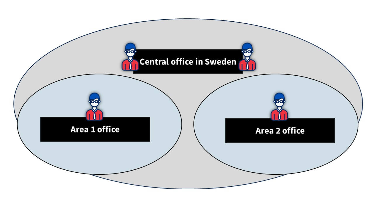
Can you share any internal projects or tools you’re working on?
The best example right now is the project that has been running for a few years now, but we’re closer to making big steps in it. It’s our hollow core design tool. It’s an end-to-end process for designing hollow cores in Tekla structures.
It starts with getting the details of the project from our ERP system. From there, you then model your hollow cores, and what’s important here is that while the tool is part of Tekla’s floor layout tool, it’s also connected to our own databases so that the hollow core profile and info about the hollow core itself comes from our databases, to ensure the quality of the data in the model.
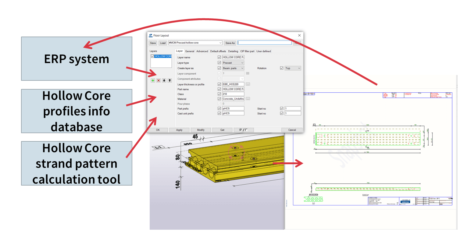
The tool is actually capable of calculating all of the hollow cores! So it calculates each one individually and applies the minimum strand pattern right there in the model. And the calculation is also done with an internally developed tool. And of course, the end result means you can generate the drawings automatically, and publish the information back to the ERP system for the factories to work with.
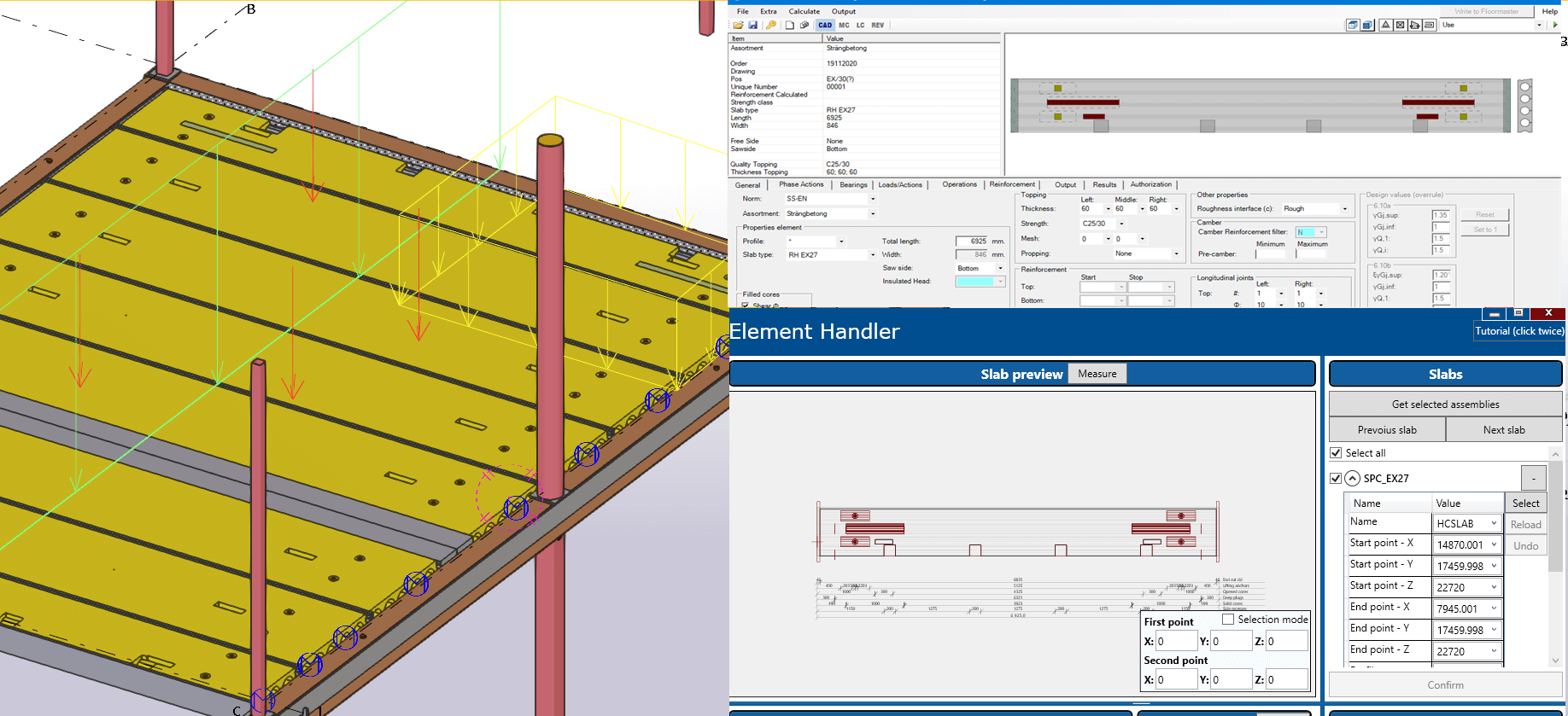
Can you give us an insight to the general workflow of your team in Estonia?
Well, that’s tricky to answer as there is generally no typical workflow! Of course, there is always the ideal workflow, but with each client comes input in a variety of ways, but ideally, we’ll get input in a usable format, even a Tekla model. But of course, the ideal solution is that we’d create the estimation (tender) project in Tekla, and it would be in a sufficient enough quality that if you need to work on it later to make it more detailed, it would actually serve as the basis for such work instead of having to start with a new project altogether.
This means we would use just one project from start to finish. I guess some of your listeners will know that sometimes the deadlines for tender projects are quite short – a few hours or maybe the next day, and you’ll create it really quickly and the result is not a very accurate model, meaning that later you will need to recreate it.
What would you say – of course, it depends on the project – but what can you say about how long it takes the company to make a tender model and take the quantities and based on these quantities, and make the offer?
From my own perspective, I think the reason tender models are sometimes not so accurate isn’t because you need to rush, but it’s more about the way you do it. So it could be that if you utilize the tool correctly, you use all of its functions, and all of its power, then creating the tender model in an accurate way wouldn’t be as time-consuming.
So you have your own ERP system and it’s connected with different systems. Can you explain how you use Tekla when you start modelling, and what kind of additional user-defined attributes do you use in the ERP, or some time scheduling statuses, costs etc?
Of everything each unit uses, the one thing that all use is the design statuses. You can take any model in Consolis, and you can see what is the Level Of Development for each element. You can see it from the model, you can see it if you’re a project manager, if you’re a modeler, or if you’re doing estimations. Regarding the link to our ERP: at the moment we publish the element to our ERP, and there we have a lot of information about the elements.
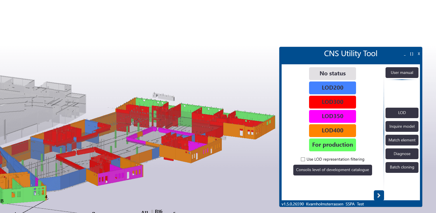
From the basics, such as element geometry and so on, but also all the properties that we add as UDAs to the elements. But the interesting part is how we get the information back from the ERP. For example, what is the production status, is the element already produced, and so on.
What system do you use for communications and sharing information?
I’d like to answer as to what I would like it to be! It’s Trimble Connect, and we are not yet utilizing it to its maximum potential. But we know that in Trimble Connect, you can link drawings to the elements. For example, you can link the calculation files to the elements, so that would be the ideal case. But today, it is not implemented across the group right now.
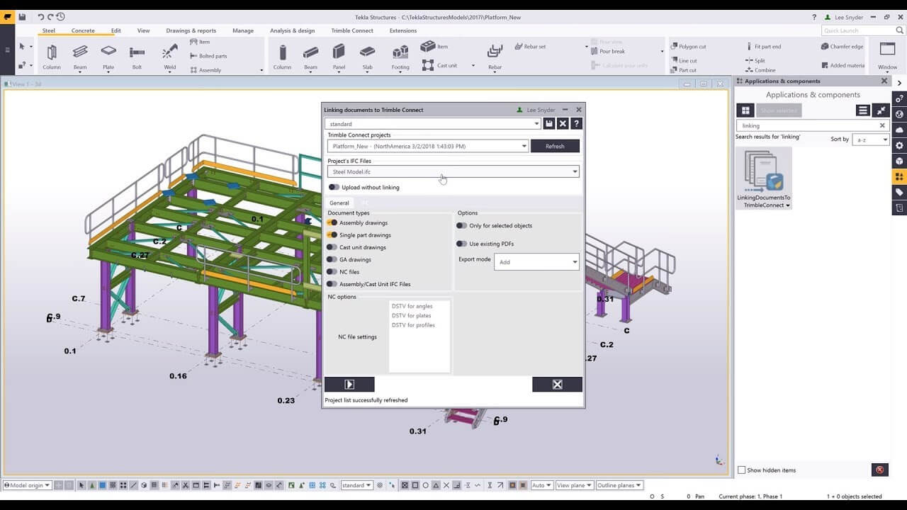
What system do you use for calculations?
There are a few different systems, but one of them is StruSoft FEM Design, which is mainly used in Sweden, but also with our Romanian teams for global calculations. For calculating the elements, we have our own internal tools for calculating the hollow core elements and also wall elements.
Do you have any knowledge on how FEM Design connects with Tekla Structures? Do you do the calculations as a model?
I know that there is a link, but we haven’t used it. So currently there is still one model in Tekla and one analysis model.
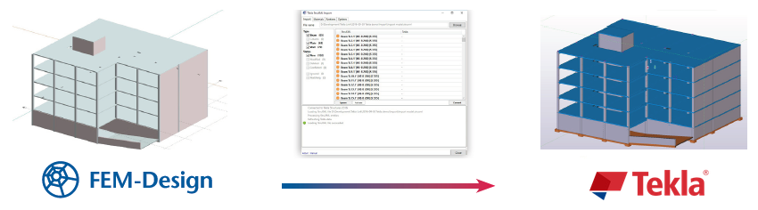
What are your tips and tricks to improve Tekla structure model quality?
My most important tip would be to use Tekla Organizer. It’s really useful for looking at the model as a whole entity. So if you want to check some parameters for some specific elements, it’s really easy to do them in a list. For example, what are the different exposure classes? What are the concrete classes? And so on. You can use it to visualize that data in the model via different colors.
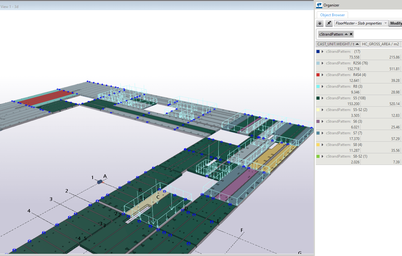
The second tip is around quality. The more effort you put into modeling and detailing in Tekla, and the more you use different tools and components you use in the modeling work, the less time you spend on drawings. A better model means fewer mistakes on drawings.
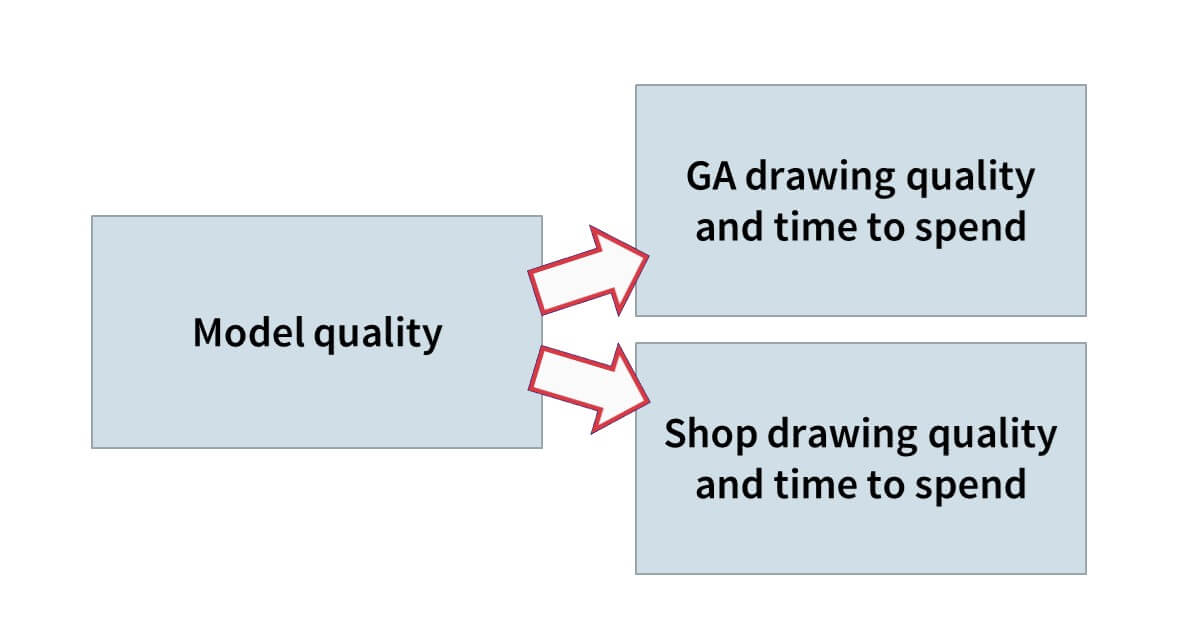
Do you think it’s possible to estimate how much time your engineers put into modeling and how much less goes into drawings?
If we take, for example, walls, which are not quite as standard as hollow cores. Generating a drawing of a wall could take from 5 minutes to many hours. The best thing to do is use the auto dimension settings and marks settings and so on. For these kinds of elements, if you spend more than 15 minutes in a drawing, then that’s already too much. It shouldn’t be called creating a drawing, it should be called generating a drawing!
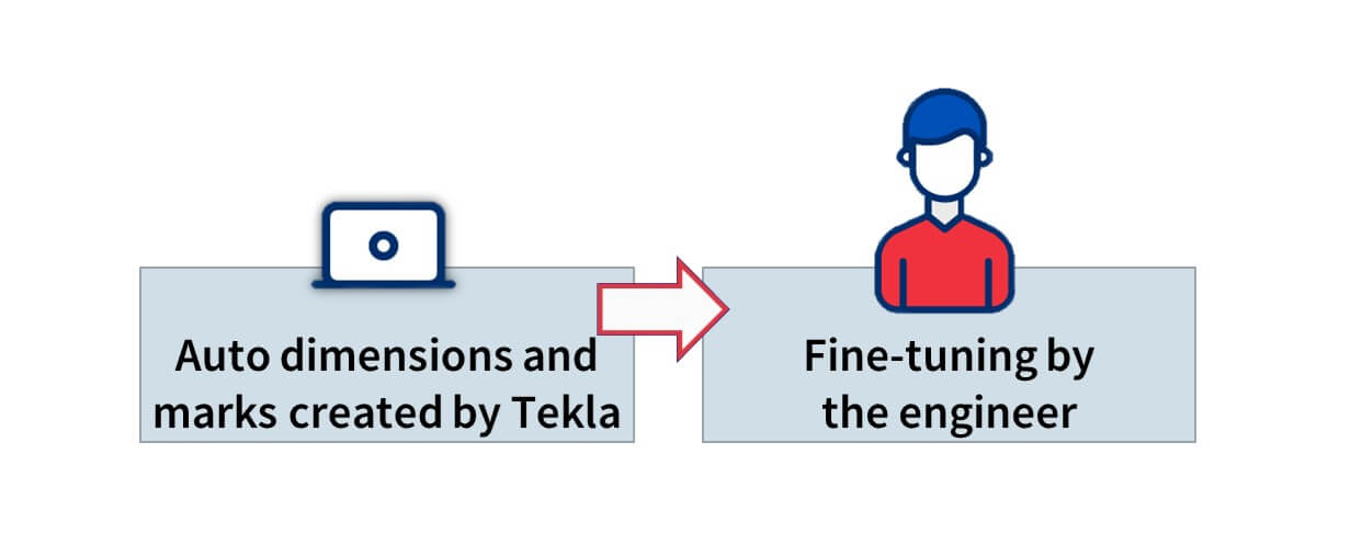
Any other tips on how to make Tekla more efficient or get results faster?
Yes. One thing that is clear is that different companies have different profiles. In Tekla, there are many different tools available in the toolbars and across the interface. For a lot of designers, you need to customize your Tekla workplace. So that what tools you have in the ribbon and what you have in the component catalog are structured in a way that you don’t need to constantly search for the ones you need most frequently. So it’s about taking the time to customize the Tekla UI to suit the work that your company does and the tools required to do so.
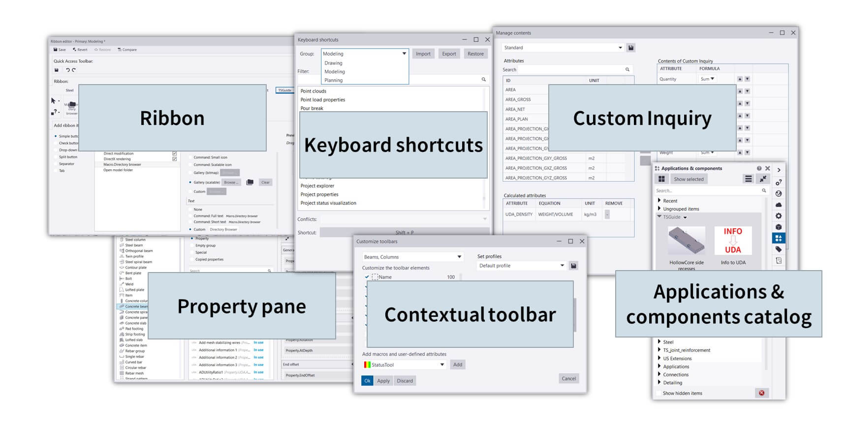
Can you share any project you were working on that was especially challenging, and how you overcame it?
I have a lot of examples of these, especially with our Swedish company. Because we are working with precast, we all know that architects are very creative people and especially with our sandwich elements – or 3-layered elements – we have a lot of very interesting facade solutions that architects want to have. This can include quite complex designs, which are easy to manufacture at the factory, but how do we ensure accurate modeling of such components? In the newer Tekla versions, they have quite a lot of tools to help you make continuous step patterns or wave patterns that an architect may want to have as part of their facade design.
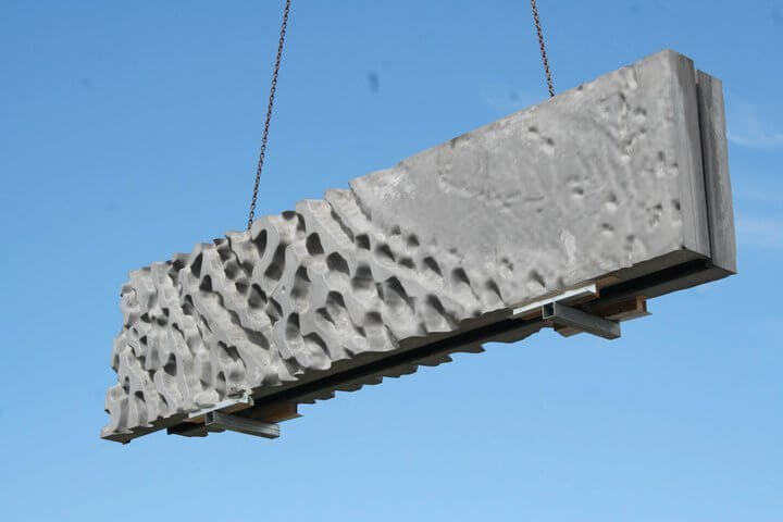
Another really interesting project we did last year – not me personally, but I was consulting a bit. We created a reinforcement model for a bridge, so it was really out of the scope of our usual work. Usually, we only work with precast, but it was a bridge in Estonia with a complex shape that was curved in different directions. It was quite a challenge to figure out the best way in Tekla structures to add rebars in these really complex curved elements. But we succeeded quite well and I must say, Tekla is quite flexible to help produce these solutions.
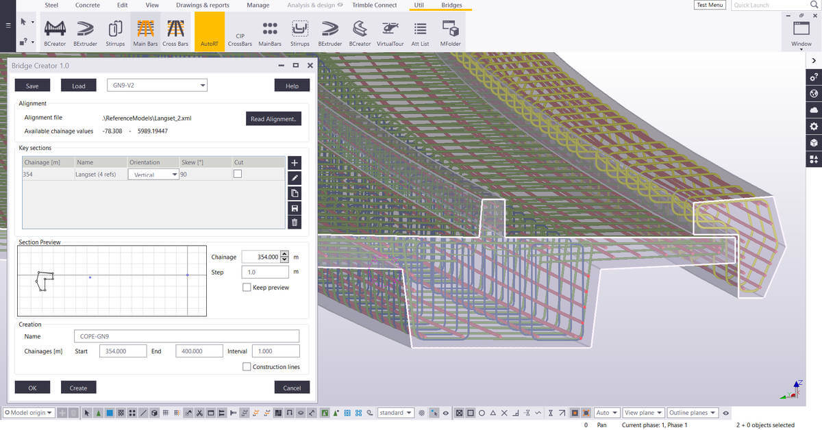
Why should companies make the switch from Autocad – which is free – to Tekla, which has a significant cost? What are the benefits of using Tekla over Autocad?
For me it would be quite tricky to explain it because I couldn’t even imagine working with Autocad again!
From the customer perspective, how drawings were produced and models were designed doesn’t really phase them. However, being able to have the as-built model is important if, for example, in 10 years’ time the customer wants to make changes to the building. You need to have the as-built model of course, and doing this with Autocad is really difficult to achieve.
But also more and more clients want to be involved in the process; it makes it easier to explain to the client what you’re doing and what you’re designing.
Have you measured things like the time taken to do a project, or the quality between the two?
When we switched to Tekla, we were not much more efficient in the beginning. That’s because in some ways, we were trying to use Tekla in the way we used to use Autocad.
So we were starting with the model, then created the drawing, and then did everything in the drawing manually. We added all the dimension lines manually, all of the marks, and a lot of modifications with hiding parts and showing parts, and so on.
But if you really use Tekla properly with all the automation, I’d find it hard to believe that I could create a model with Autocad more efficiently and with fewer mistakes than with Tekla. Especially with regards to quality, because in a 3D model it’s far easier to check for conflicts, especially as we get IFC models from other tools much more frequently now.
For example, ventilation design, piping, and so on. So if you get the up-to-date IFCs from the other designers weekly, then you can just easily check in the 3D world if you have conflicts with the other design parts. That is something that’s really hard to do in the 2D world of Autocad.
What are the company’s plans for Tekla internally for its development? Where are you planning to take it?
We’ve been thinking about this quite a lot. We are doing a lot of different developments, we have a huge number of designers, in different countries who are working in different ways, but it seems to us more and more that we haven’t had the data on where is the time going in the models? How can we use it more efficiently, how can we tell if the designers are using the tools that we provide them with?
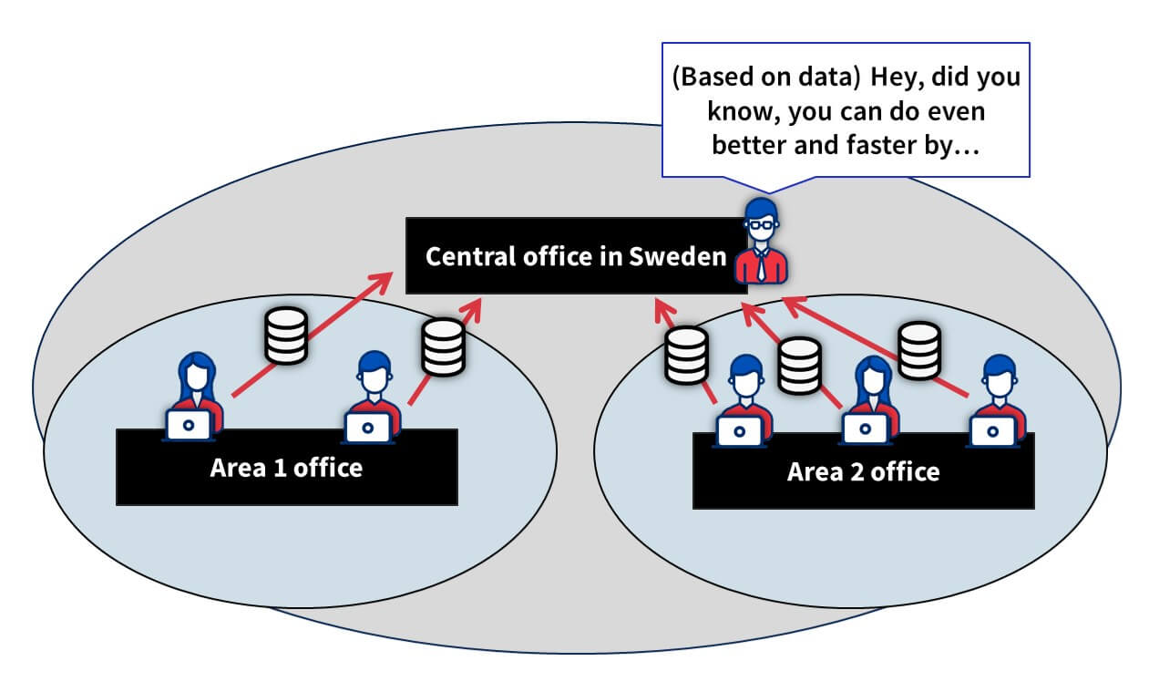
So there is one thing we’ve started where we can gather some information about the usage of Tekla, and through that, we’ll be able to see through all of our designers how many custom components they were using during that period. And also if we create some automation settings for drawings, we can check and see if these settings are being used.
And it’s not just about tracking the tools we have created; it’s also about understanding which tools we are NOT using. So that we can compare between different business units and companies, that maybe there are some very productive practices one company is using and others are not (usually it’s because they are just not aware that it’s there), so then we can spread that knowledge and as such, improve efficiency and accuracy and so on.
Really use the information to make decisions, not based on feelings.
The same goes for following the information about projects and Tekla models. Create reports automatically, for example, daily, and use other tools for analyzing the data. For example, you can have live up-to-date dashboards for different models, where you can use data about the history for making project future predictions.
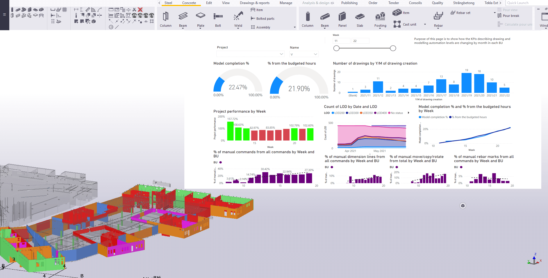
Generally in the BIM world, or globally, how do you see things are going?
A lot of things will happen! But there are definitely a few standing points to look at that from; in the world we’re in right now, we all know that we need more and more information for different reasons and purposes.
If I were to start with the environmental impact that the industry is having on the world itself, then more and more customers – especially in the Nordic countries, and others – really want to get information about their buildings. For example, the carbon footprint of the building. And, if you don’t have a proper model with accurate, thorough information about different points such as where is the concrete coming from, where is the steel coming from, what embeds are you using in your elements – if you don’t have that information, then it’s impossible to calculate any kind of carbon footprint.
So that’s a major thing in BIM; that for each material or element, you put in the model – there is some kind of connection to your IDE or database – what really is the material being used?
One example is even what factory the component is manufactured in. For us, we produce pre-cast elements, but for the customer, there’s a big difference if we produce it in a factory 2000km away from the site versus at a factory 200km from the site, owing to the amount of carbon emitted in the transportation. So realistically, if I were to go into the ERP and change the factory the element is going to be produced in, the client then can see an tangible difference in the carbon footprint of the construction of the building.
AUTHOR
FIND THIS USEFUL? SHARE IT!
[Sassy_Social_Share_Pro]
YOU MIGHT ALSO LIKE
Here is the list of our favorite features and updates in Tekla Structures 2021.
ARVE error: Mode: lightbox not available (ARVE Pro not active?), switching to normal mode
CONTENTS
1. The list of “Top 5 + next 5”
- Batch editor to copy element edits to other elements.
- Dimension associativity rules during manual dimensioning
- Exclude template from layout to modify only one drawing
- Create / show / open shop drawings from contextual toolbar
- New shape catalog
- Clash Check Manager new settings for selecting object types
- New clip planes to control view depths
- Ctrl + C to copy drawing Content Manager selected rows to the clipboard
- Copy or move detail section marks
- Rebar sets improvements
- Follow the edges – the modifier or guideline follows the leg face edges that are located between its endpoints.
- Minimum bar length
- Leg connection tolerance
- Changing the direction of splitters, modifiers and guidelines
- Grouping advanced settings
- XS_REBARSET_SIMILAR_GROUPING_NUMBER
- XS_REBARSET_SIMILAR_GROUPING_TOLERANCE
- XS_REBARSET_TAPERED_CURVED_GROUPING_TOLERANCE
- XS_REBARSET_TAPERED_LINEAR_GROUPING_TOLERANCE
2. Trimble official links
- Release notes – https://teklastructures.support.tekla.com/2021/en/rel_cover
- Demo videos (coming soon) – https://teklastructures.support.tekla.com/video_tutorials/top_new_features_anon
Go also read our previous article Tekla tip 63: symbols.
AUTHOR
FIND THIS USEFUL? SHARE IT!
[Sassy_Social_Share_Pro]
YOU MIGHT ALSO LIKE
Symbols are everywhere. They are a universal visual language for communicating concepts and instructions without the need for text of one type or another.
Things are no different in Tekla Structures. But did you know there are two ways of using symbols in Tekla? Which technique do you use? Maybe it’s time to switch? You can watch the demo video, or read the article below.
ARVE error: Mode: lightbox not available (ARVE Pro not active?), switching to normal mode
Today’s article is all about minimising mistakes in your work. Symbols are an essential component of what you do in Tekla, but even if you do everything right, things can still go wrong. Let’s find out why.
CONTENTS
1. WINDOWS CHARACTERS
The first method of working with symbols is using Windows characters.
It’s easy to open the Windows Character Map app; simply press the Windows key on your keyboard; type char; then press enter. You could also right-click the app and pin it to your taskbar if you’d prefer.
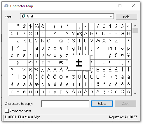
Find the symbol you’d like to add to your work. Then, look in the bottom-right corner of the app to find the keystroke; in the case of the example above, it’s (left) ALT + 0177. If this is a symbol you need frequently, this will be the fastest way of entering it, and you will probably end up knowing a few of these keystrokes by heart.
Note that when entering the numeric part of the keystroke, it must be entered via the number pad on your keyboard; the numbers above the letters will not work.
Everything seems fine so far; so, what is the potential issue with this?
Well, it comes down to languages. Depending on your workplace, you could be dealing with different colleagues who have different languages active on their computers.
For example, in Estonia where I am based, it’s quite normal that I will have colleagues with their language set as either Estonian, Russian, or English. The problem is that many Windows characters have different keystrokes in different languages, meaning that if I enter a character using one keystroke – for example, the diameter symbol – and a colleague opens that same drawing with their language set to English, that character can change to something completely different 😱
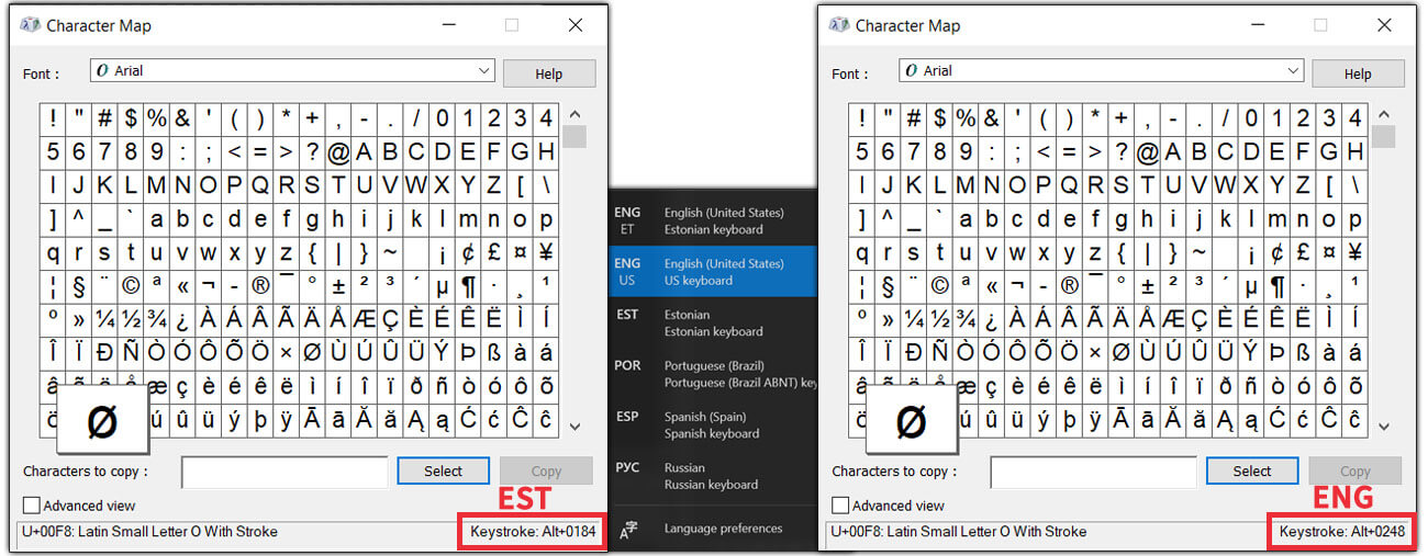
Obviously, this is not a good thing; so, if your work environment has this situation, then it is probably best not to use this method. However, if you are confident that everyone uses the same language, then it can be a good solution 👍
2. TEKLA GRAPHICAL SYMBOLS
The second option is to use Tekla’s graphical symbols.
Tekla already has a library of select symbols, and beyond that, you can use Tekla’s Symbol Editor to modify them, or create your own symbols.
Using these symbols is fairly straightforward. In drawing view, you put the mark, then choose the symbol you want. Select the symbol file, and from it, the symbol you need. Similar to Windows Character Map, each symbol in the file will have its own reference number.
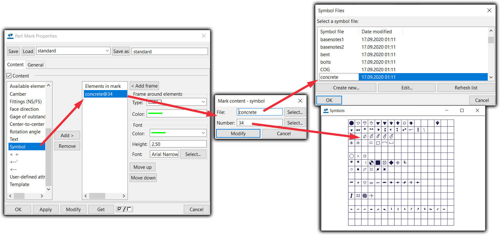
It sounds good, and for the most cases it is; but the downside to using this technique is if you have custom symbols, and Tekla doesn’t know where they are – then unsurprisingly, you’ll have problems!
So in this case, it’s a good option to use this symbol file method, but keep in mind that – especially if you have custom symbols – every Tekla user needs to know where that file is stored. I recommend to keep this symbol file with each Tekla model and then let Tekla search for this symbol file from this model folder. Use “set DXK_SYMBOLPATH=…” in user.ini file to set the location of Tekla symbols. Read more from Tekla support article.
Why keep files in the Tekla model, and not somewhere else? Take a look at my other tips and tricks on where to keep your files; with the Tekla template model, in a firm folder, or somewhere else.

3. CONCLUSION
So, did you learn anything today? I hope you got a good idea of how these different symbol methods work, and which of them you’d prefer to use.
Perhaps you’ll change what you do as a result of this? Or, you might gain the confidence that the current way you do things is the right option for you 👍
Go also read our previous article Tekla tip 01: firm folder vs template model.
AUTHOR
FIND THIS USEFUL? SHARE IT!
[Sassy_Social_Share_Pro]
YOU MIGHT ALSO LIKE
In this article, we’re going to break down the pros and cons of using a firm folder and the template model, for storing all the various files and settings for Tekla Structures.
After exploring those options, we’ll give you our recommendations. You can watch the demo video, or read the article below.
ARVE error: Mode: lightbox not available (ARVE Pro not active?), switching to normal mode
Additionally, download and print out this short and illustrative PDF one-pager that you can use to remind yourself to use these tips, or to help explain them to someone else.
CONTENTS
1. Making changes at the company level
(Template) model folder
The key benefit of using this method are that there is greater control over all the content, making it the safest choice.
This means all project models will always be the same as when you were working with them, and you can come back at any time and view it whenever you need to.
So what’s the downside? Well, it’s that it takes more time to set up and manage. Files must be copied, changed, and removed – precisely – in all the projects that you want to be affected. Depending on the number of projects, this could become quite a daunting task (if you don`t automize it)!
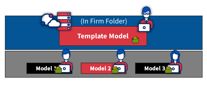
Firm Folder
As opposed to using a template model folder, the best thing about using a firm folder is that it’s much faster; you only need to cope, change, and remove files in one place; the firm folder.
The flip side is that sometimes, making those changes might result in some unwanted surprises in your ongoing connected projects, which can be tricky to resolve.
A few more years down the line, it’s likely that there will have been changes made to the various files stored in the firm folder. That can mean that you won’t be able to view a model in the same shape as you made it in the past, in case you believe that will be important to you.
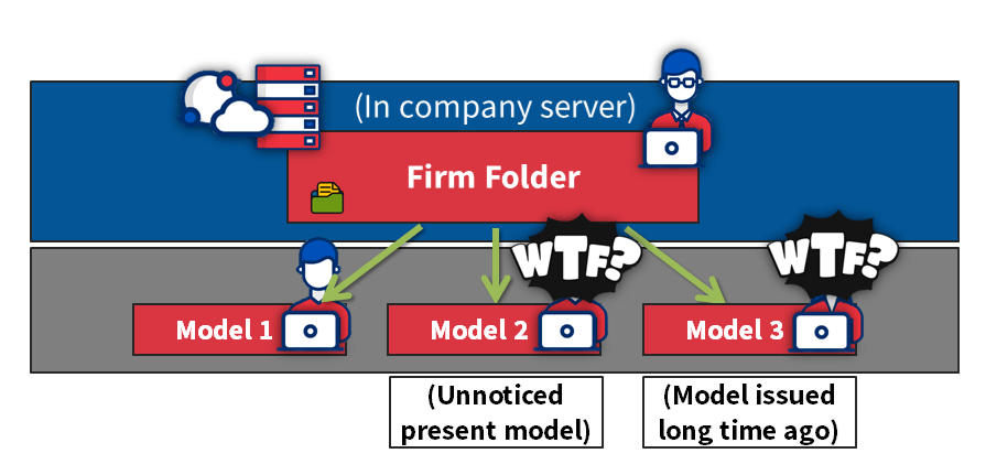
2. Different requirements for different customers
(Template) model folder
Using the template model folder method allows you to create country- or customer-specific setups, in much the same way as Trimble does different template models for engineering, precast, steel, etc. All the files remain in one place.
This means you have better control of which files and settings are seen, and therefore usable in the model.
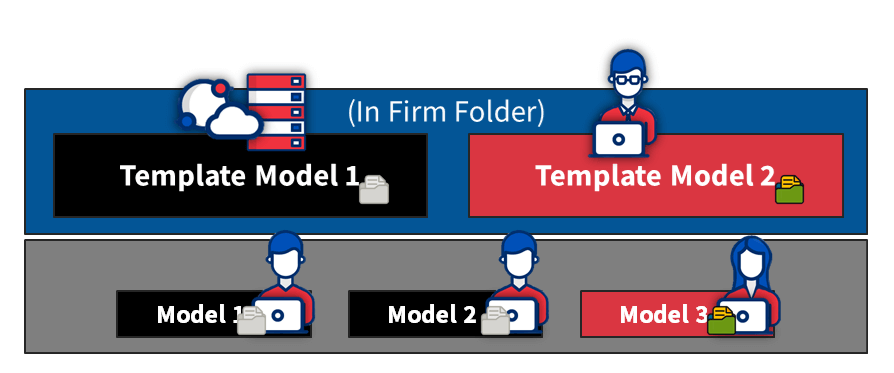
Firm folder
Things start to get more complicated using the firm folder method.
If you use the firm folder method, you can create different project folders for creating projects with a different style (e.g. different countries and different fabricators may have different output requirements). This results in some files being stored in the firm folder, while others are taken from different project folders. Having the files in different locations makes things more difficult than they need to be.
The end result is that unnecessary firm folder files will be shown/included in these projects.
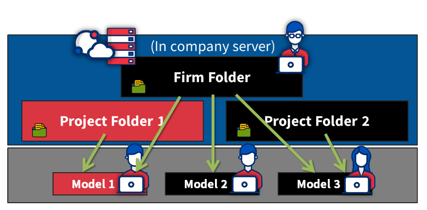
3. Making changes at the model level
(Template) model folder
With everything in the one place, making changes at the project or model level is super easy. All the files are just in the model folder!
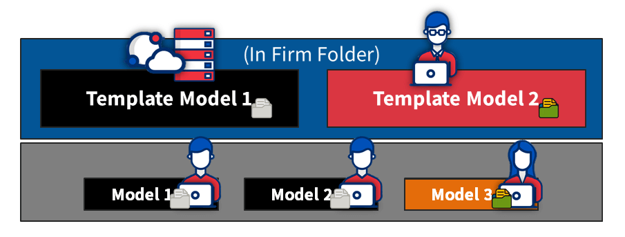
Firm folder
When making changes on a model level, you can only do it within model folder files.
But remember – now you’ll have some files (e.g. template files) in the firm folder, other files in the project folder, and even more files in the model folder.
Sometimes, even more folders are used, and it really gets complicated for the user to know which file and where it’s being used!
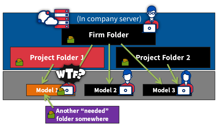
4. Working remotely or sharing model
(Template) model folder
Easy; just copy and send all the model files, and it works so well because everything is already included!
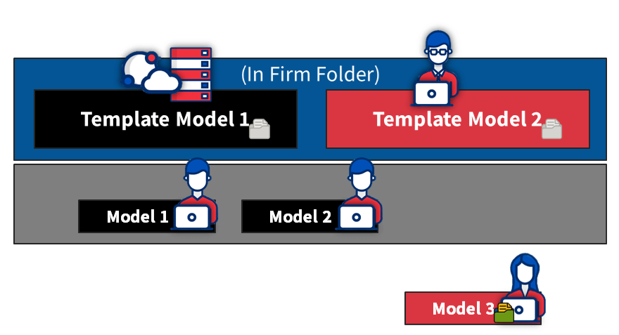
Firm folder
If you opt for remote work, you’re going to need a VPN connection to your firm folder. But remember – without internet access, you won’t have access to these critical files.
There’s also the chance that some files will be missing, and then everything won’t work correctly.
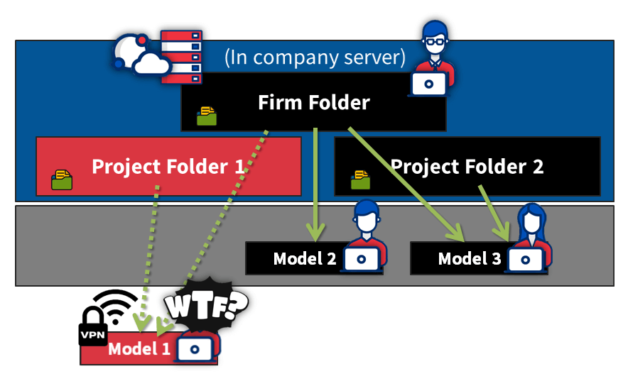
5. Speed
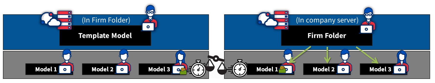
(Template) model folder
If you are using the single user model, then all the files you need are stored locally on your computer. This is by far the fastest way to go, because you don’t need to fetch any information from remote sources.
Tip: For multi-user projects, we recommend using Tekla Model Sharing.
Firm folder
Even with a fast in-house server and speedy connection, retrieving assets from a network location is still going to be slower than if you had it all stored on your computer.
Of course, it gets even slower if you need to use a VPN connection.
6. Security
(Template) model folder
Here’s one area where the model folder falters somewhat.
Say for example an engineer leaves your company, or worse yet, decides they want to share your company-developed files externally. Well, it’s going to be easier to do that, because all your content is nicely kept in the one place, ready to go.
Firm folder
The inherent nature of the firm folder method is that it’s more complicated, as the files are stored in multiple locations. This means that it’s somewhat more difficult to get all the necessary files together in order for them to be shared.
7. Model size
(Template) firm folder
The model size is overall a little bigger, because all the required files are in the model folder.
Firm folder
As some key files are stored in the firm folder, the model size tends to be a little smaller.
When it comes to the firm folder
The firm folder can be located in several different places, including:
- On the company server (for bigger companies the most used option and in this article used case)
- Hosted in cloud-based file sharing services like Google Drive and Dropbox
- On every user’s computer
- In Trimble Connect
Considerations when using Google Drive, Dropbox, and others
These services constantly update the files on the local computer, which is great, though it does require an internet connection.
We and CS Wilson (CS Wilson Draws-Tekla Tech Talk: Episode 03) recommend to pause the updates for working, or you may have unintended conflicts arise.

Considerations when the firm folder is stored on the local computer
When there’s only one user, there’s no problem storing it this way.
Keep in mind, though, that when there are multiple users, then you must make sure that everybody’s firm folder is kept up to date, otherwise it could result in errors.
Our recommendations
As a best practice, we recommend storing as many files and settings as possible in (template) model folder. And template model is located in firm folder.
Then, apply “read-only” permissions to the firm folder for protection. Make a rule that only one person – the BIM manager – can add, modify, or delete its contents. Or it gets very messy fast, if everyone will start doing their modifications.
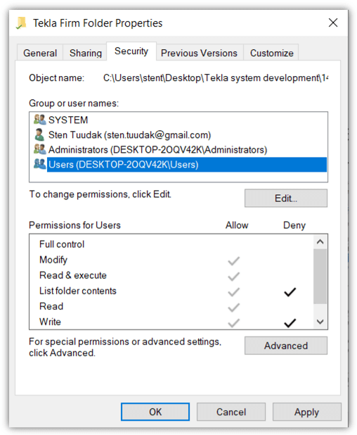
When one person has control over what’s going on in the firm folder, there is much bigger possibility that things are being kept consistent and clean.
Go also read our previous article Tekla tip 36, selecting objects.
AUTHOR
FIND THIS USEFUL? SHARE IT!
[Sassy_Social_Share_Pro]
YOU MIGHT ALSO LIKE
Selecting objects in models, drawings, and lists is an absolutely fundamental action in Tekla Structures.
So much so, that learning the most effective ways to do so will save you many hours in the long run! You can watch the demo video, or read the article below.
ARVE error: Mode: lightbox not available (ARVE Pro not active?), switching to normal mode
Additionally, download and print out this short and illustrative PDF one-pager that you can use to remind yourself to use these tips, or to help explain them to someone else.
CONTENTS
1. AREA SELECTING DIRECTION
There is a difference if you area-select objects in a model or drawing from left to right or from right to left. But there is no difference if you start picking the area from top to bottom or bottom to top.
- If you select the area from left to right, Tekla will select only the objects that are entirely inside that area
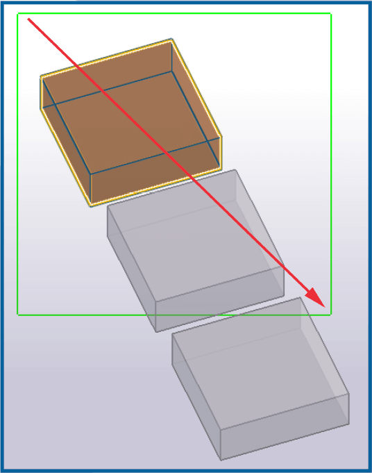
- If you select the area from right to left, Tekla will select all objects the area touches.
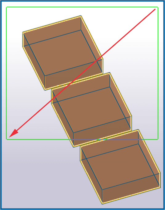
2. SELECTING WITH CTRL / SHIFT
This tip will work in models, drawings, lists, and even in Windows generally (e.g. selecting files or folders).
It works both ways; you hold down the CTRL or SHIFT key, and then select objects one by one with your mouse (or use area selection to select multiple objects with one go).
The difference between holding or without holding CTRL or SHIFT key down is that if you hold one of these keys down, Tekla will keep previously selected objects still selected.
- Holding down CTRL while selecting inverts the selection, meaning if the object was not selected before then it will be selected, and if the object was selected before then now it will be deselected.
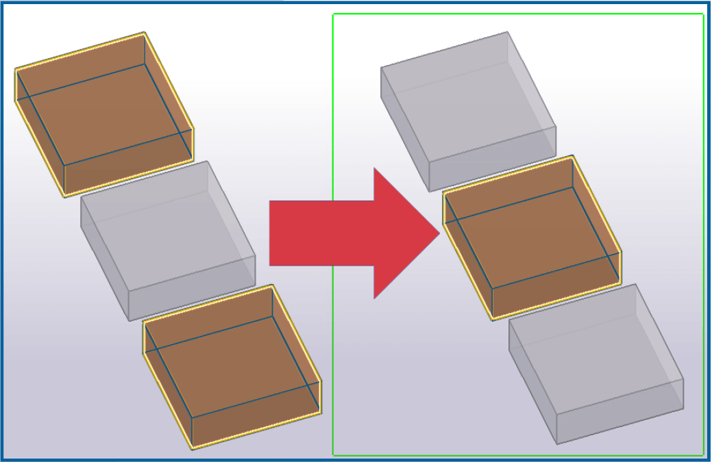
- Holding down SHIFT while selecting will select the object in any case. It doesn’t matter if the object was selected or not before; after selecting with holding shift key down, it will be selected.
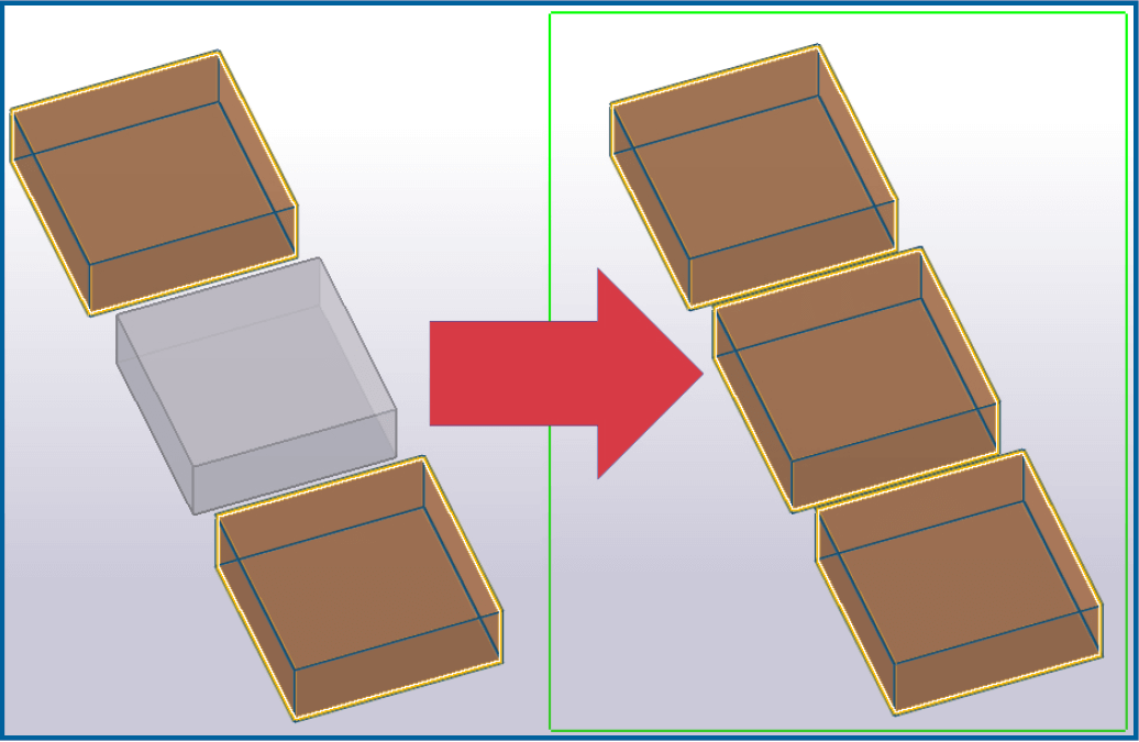
3. SELECTING WITH CTRL / SHIFT IN A LIST
- Using the SHIFT key in lists is a little different. Select one object in a list, then hold down the SHIFT key and choose any other object in the list. As a result, Tekla or Windows generally will select these two objects and all other objects between them.
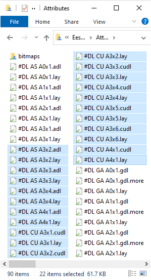
- If you hold down CTRL then Tekla or Windows will select or unselect only the object(s) chosen using area selection.
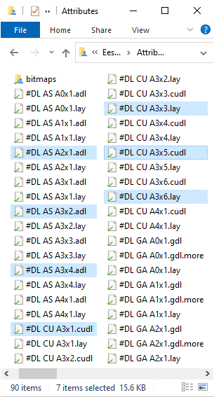
4. SELECTING ALL WITH CTRL + A
This keyboard combination works in Tekla models, drawings, lists, and in Windows generally.
Sometimes there are too many objects and it may be time-consuming to zoom out in the model or drawing space, or do a lot of scrolling in order to select all objects.
Instead, you can just press CTRL+A and all objects will be selected. In the model space, you can use also selection filter with Tekla selection switches in order to select only one type of object in the whole model.
5. USING A COMBO
- There are many cases where you might select all objects using CTRL+A or many objects using the SHIFT key, and then unselect unwanted objects by holding down CTRL key.
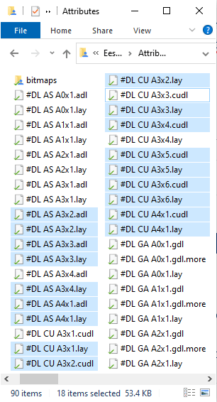
Go also read our previous article Tekla implementation/audit checklist.
AUTHOR
FIND THIS USEFUL? SHARE IT!
[Sassy_Social_Share_Pro]
YOU MIGHT ALSO LIKE
We’ve helped produce one Tekla official environment, and since 2017, more than 10 company level localizations.
From producing these localizations, we’ve helped companies get started from scratch and quickly get the output the market is demanding from them. Later, seeing the value, we have brought up their Tekla efficiency to the next level.
Over years doing this work again and again, we have noticed a pattern and we have developed our extensive (more than 20 pages long) “Tekla Implementation Checklist” that we’ve used both for doing an audit or implementation plan with:
- new companies starting out with Tekla Structures in their organization, and want to get going as quickly as possible, and,
- companies already using Tekla Structures that want to find ways to improve their system and make it more efficient.
Now we’ve decided to make this checklist public and share it with you for free. Use this checklist to evaluate your company’s Tekla situation and we’re sure you’ll get some new ideas on how to improve the system and get Tekla working better for you.
Keep reading about our three step implementation process that has evolved with years of experience, and how to use this checklist on the way.
CONTENTS
WHY IS LOCALIZATION IMPORTANT?
Tekla Structures is not the cheapest software on the market, and for most new users, it may be a little difficult to see a good return on investment.
Often they say that the price is higher than other systems and it still takes the same amount of time – or even more – to get the same project done. But other companies who have used Tekla Structures for some time realize the benefits and laugh at the thought of going back to CAD software!
So why do some companies get more value from Tekla than others?
I believe that the difference is because of two main factors:
- People – what people are used to working with, how they feel about it and how good they are with the software. Some people adopt new ways of working faster than others, but if there is a combination of motivation to use Tekla and good training with lots of practice, they will become effective.
- Software – Tekla is a very powerful tool that has many possibilities, but out of the box it doesn’t do everything for you automatically. Ultimately, Tekla needs to be configured and tailored to your company’s needs. It’s your job to tell Tekla how you want things done. You need to customize and automate it according to your needs, in order to let it automatically do as many tasks as possible for you.
At Tekla HQ in Finland they have developed this fantastic tool and offices all over the world have done ~30 environments to customize it for local area needs.
Still, every company has its own specific needs, and in order to get most from it, localization at the company level is heavily recommended – or in some cases even inevitable.
The good thing is that you do the implementation only once, and all your future jobs will be affected positively without any extra effort. Tekla automation will help engineers be more productive and at the same time, the project quality will increase through the reduction of mistakes.
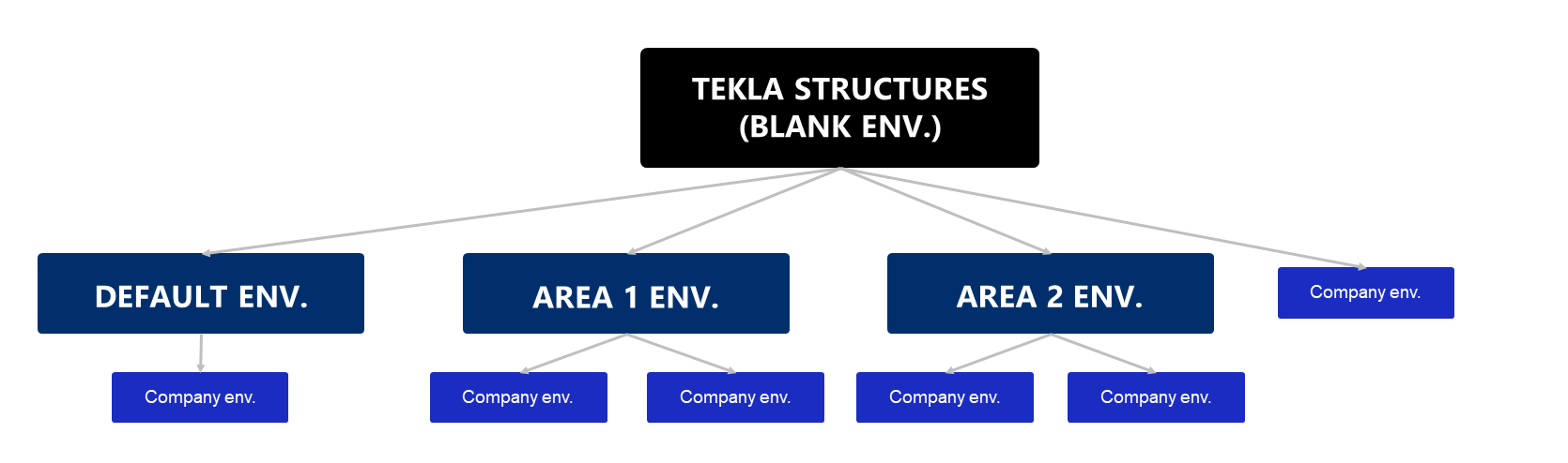
STEP 1. MAP THE SITUATION
The first thing that needs to be done is to map the current situation.
With a new Tekla user, this task is easier, as they are starting with a clean slate.
With an existing Tekla user, a full audit needs to be performed by following all the steps outlined in this document. It’s necessary to have a good overview of what has been done already to see what is missing, and at the same time, we want to reuse all the work that has been already done as much as possible.
Aside from investigating the Tekla-specific system setup, it’s very useful to get an overview of the company and its clients at least at some level. It’s also useful for the next steps – offering improvement options, prioritizing them, and finally combining them to into one structured and prioritized development plan. Depending heavily on the company type and specifics, the process usually looks like this:
- We go through the current workflow from beginning to end. We don’t consider ourselves to be business consultants, but in many cases we can provide some good ideas that we have seen working well in other companies on how to get more benefits from the software for the whole workflow. There may even be changes we recommend at a higher level in order to obtain maximum benefits to your company as a whole, and subsequently for your clients.
- Looking at the areas that you see the most problems in, and where you are looking for efficiency improvements. These two points should be always be kept in mind, in order to improve the company. How can we improve our efficiency and minimize project mistakes?
Finding the things of extra value that you can offer to your clients which your competitors don’t provide. We can’t always raise the prices for our work, but by offering this extra value, we will stand out from our competitors. The aim is to get a better reputation and get more work offers without lowering prices.
In your checklist…
Write a number between 0-5 to rate your current situation and add comments below, like this:
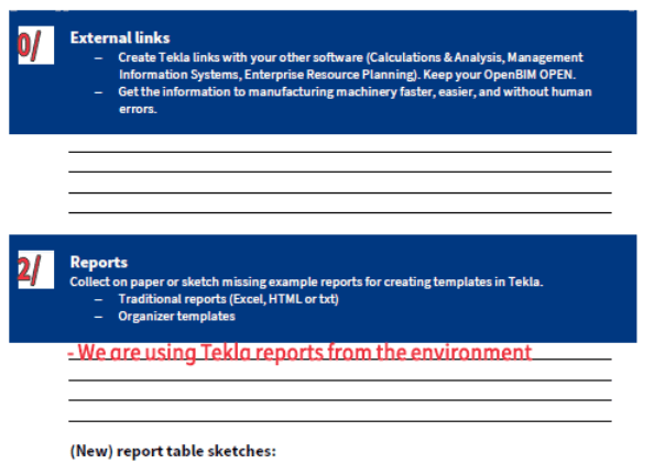
STEP 2. IMPROVEMENT POSSIBILITIES
After mapping the current situation, it’s time to brainstorm or map all the improvement possibilities.
The base idea or usage of Tekla Structures is the same everywhere, but given that it’s such a capable and customizable software, it can be interesting to see how different companies are inventing different ways of getting more benefits from the same system.
If you already have this top-notch tool, using it to its full potential will ensure it’s as useful and profitable an investment as possible.
In your checklist…
Write all the ideas you can think of to improve; something like this:
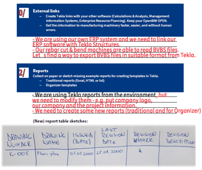
STEP 3. PRIORITIZING
The last step before implementing changes and improvements is to prioritize the tasks.
The crucial tasks should be addressed first, followed by the tasks that provide the most value or benefits with the least time/money investment.
Our main goal is to ensure you will get more value and maximum return on your investment.
Each company case will be different, but often the priority order at a high level will look something like this:
- Getting Tekla Structures and licenses working on the company system and on everyone’s computer.
- Set common modelling rules and the most important guidelines.
- Essentials to fulfill basic market needs and get at least the same output as you got before with AutoCAD. This includes drawing and report templates with printing and exporting to DWG or PDF.
- The extra value that you can provide to your clients, without extra effort – e.g. OpenBIM IFC model or some other export formats, or additional information (Excel table/paper, or even in a visual way).
- Automate drawing creation: the drawing style, marks, and shop drawing dimensions. Usually, we start with general arrangement drawings and continue with shop drawings. The aim is to get drawings as fast as possible and minimize human errors. Some degree of human intervention is always needed, but utilizing the speed and ability of the computer to do the work according to the rules is a great productivity gain.
- Automated modelling: create pre-saved settings for existing tools or develop new custom components/macros/OpenAPI development tools to get more things done automatically and faster, with fewer errors. With different tools and settings, we can also speed up the modelling component and minimize possible errors or inconsistencies in the model.
- Documentation, e.g. rules, checklists, instructions, and examples. Document and standardize the processes to ensure that all projects will be done in the same manner. This is how every teenager working at McDonald’s restaurants can produce burgers with exactly the same taste and quality anywhere in the world.
- Training materials and video tutorials, especially for new employees. Once you have a successful system, very soon you need more and more skilled employees.
In your checklist…
You can prioritize each topic, or even better, add priorities to each idea in this topic (if you have there more than one). Something like this:
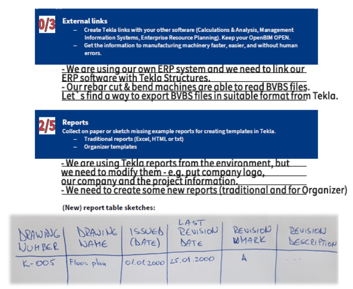
BONUS – RECOMMENDATIONS
In the planning stage, we highly recommend including people with experience in setting up Tekla environments, and anyone with knowledge on best practices or possible mistakes made by other companies. It’s far more efficient to include these people in the planning stage in order to avoid additional work down the line.
Spending a little more time on planning and getting it right the first time saves you a lot of time and money later. This principle is demonstrated well in construction, where spending more time on decisions at the beginning are much cheaper than having to make remedial changes later. Remember – measure twice, cut once!
Doing the situation audit and plan is only the first step. Without any action, it will remain on paper as a cute plan without any practical value. Use the momentum that you have right now and start with the first small steps as soon as possible. Based on priorities divide your plan into smaller phases that is easier to start and complete. If you don’t do it right away, the probability will rise that you will not do it in the future either. Every month that you don’t use Tekla to its full potential means your engineers and detailers are also inefficient and not as profitable.
We understand your situation and want to help. That’s why we provide this most important checklist without cost. Use it wisely, and if you have any questions, feel free to contact us contact@tsguide.eu – we’re more than happy to assist!
If there are no highly skilled Tekla ninjas in your company or they are quite busy with ongoing projects then go and check out how we could help you – https://www.tsguide.eu/tekla-company-environment/
Go also read our previous article Free Tekla education “Getting started” step by step guide.
AUTHOR
FIND THIS USEFUL? SHARE IT!
[Sassy_Social_Share_Pro]