Tekla Podcast #1 – Consolis CES Esonia advanced Tekla system and development (Morten from CES Estonia)
17 min read + 58min interview
Consolis is a European leading industrial group providing sustainable and smart precast concrete structures. They are specialized in the design and manufacture of high-performance precast concrete products.
Morten Kaasik has 5+ years of experience as a structural engineer with Tekla Structures and now he is Design Modelling Tools / BI Development Manager at Consolis CES Estonia.
Start watching the interview video here:
ARVE error: Mode: lightbox not available (ARVE Pro not active?), switching to normal mode
or listen it in audio format here:
Don’t have time to watch the whole pod? Skim the questions and answers summary in written format below! 👇
How did it go in the beginning with using Tekla in your company? What advice would you give to a company considering implementing it?
For us, it was probably a bit simpler than for most. The Swedish side of the business had already built their own Tekla Environment – settings, drawing templates, and so on. The big obstacle was that everything was in Swedish. Having said that, the technical vocab was there as we had been working with Swedish templates in Autocad, so it wasn’t a huge obstacle.
The biggest challenge was that I was the only one who had used Tekla before, as I had been involved in some other projects on Consolis using Tekla, so I knew some basics like how to reinforce elements and how to create drawings, but I was still mostly learning on the go. I think we still look back on this project and we believe that if we were going to do this project again, we wouldn’t do things any differently because we did not have the knowledge to realize there was a different way to do things!
Of course, in hindsight it’s easier to say things like yes, we would have automated things like drawings and how to use more components, but still we were mostly learning as we went.
During this first project I actually started creating custom components; I had no experience with that but it was about looking really critically at what you were doing. For example, if I had 500 wall elements, and wanted to add a very specific detail to all of them, I started to think “Hey maybe there is a better way?”. For example, in Autocad we have blocks. So I Googled a bit and saw that you could create custom components. I must admit my first custom component was quite ugly! But it did the job.
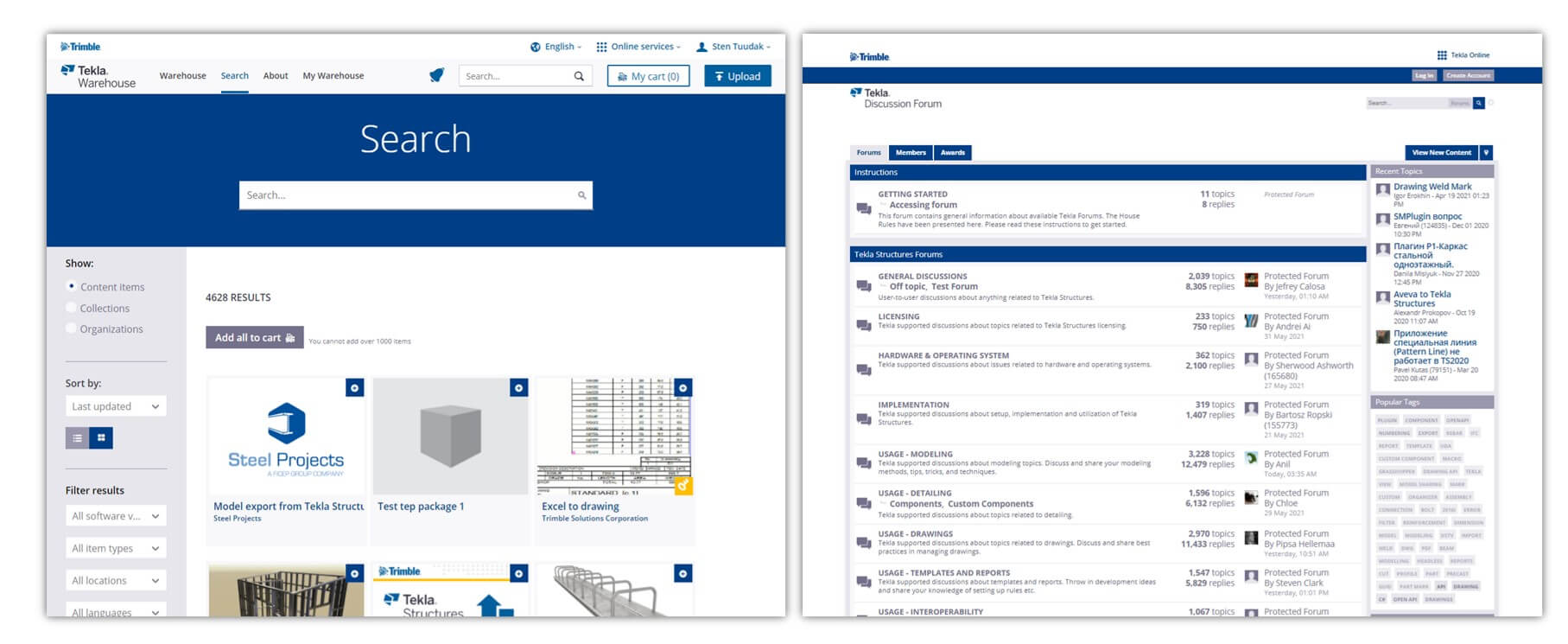
But my advice to anyone who starts to implement Tekla at their company would be to do planning before anything else – which templates you will be using, which environment you will be using. And if you have some very specific solutions you need to create, then definitely check the Tekla Warehouse (warehouse.tekla.com) because there might be some tools available that could help you. if not, then definitely look into the Tekla forums (forum.tekla.com) where there is a lot of advice and assistance to help make your work better. Look very critically – don’t use Tekla as you used Autocad; make sure you unleash the potential of Tekla.
What’s the most important thing when you want to work with Tekla? Development? Training? Hiring expensive engineers? Internal training?
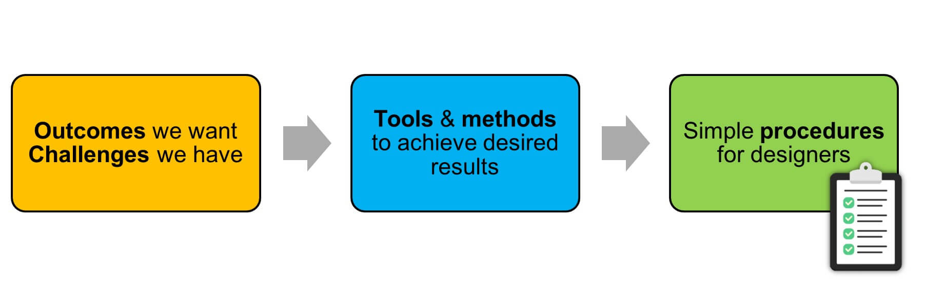
The way I look at it is that Tekla is a huge toolbox. One of the most important things to do is identify the needs of your company and the challenges you need to solve, and then from all the tools in this huge toolbox, identify the main ones that you should be using. Next, create simple procedures that all designers can follow – the larger your company, the more important this is to help ensure consistency, accuracy, and efficiency.
What about developing custom components versus just doing them yourself? How to judge the ROI?
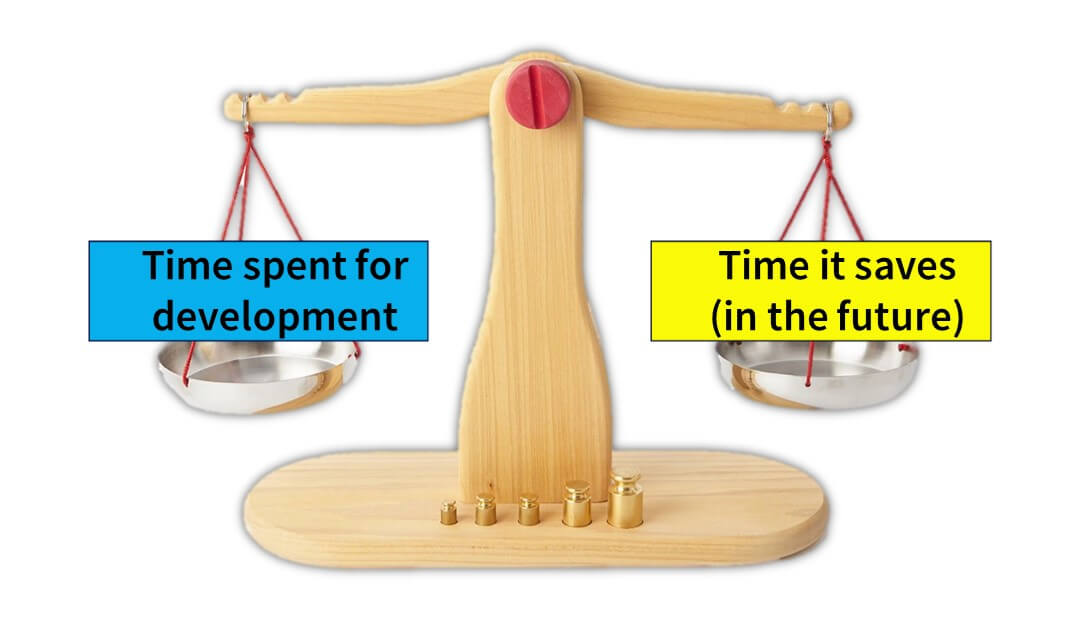
Simple components can yield tremendous benefits via quick wins.An example would be that doing the drawing automation would take, say, 24 hours to develop. But if my project hours are 1000 hours, and if doing this 24 hours meant I would save 100 hours in design work, then it was a no-brainer. But if it’s not so clear that it’s a benefit in the short term, then try to assess if it could apply to more than 1 project, eg. If it’s a tool or a setting that I can use in all my design projects, then ultimately it would be worth doing.
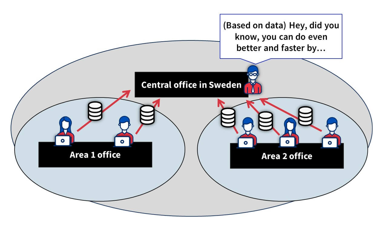
You have around 45 engineers in Estonia. If one creates a great tool or setting, for example, how are you ensuring that everyone can have access to it so that all can benefit?
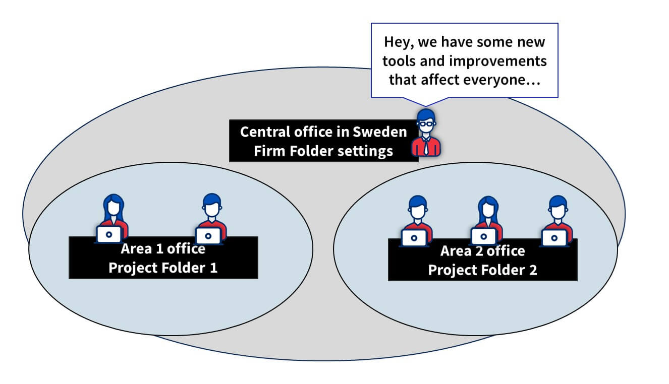
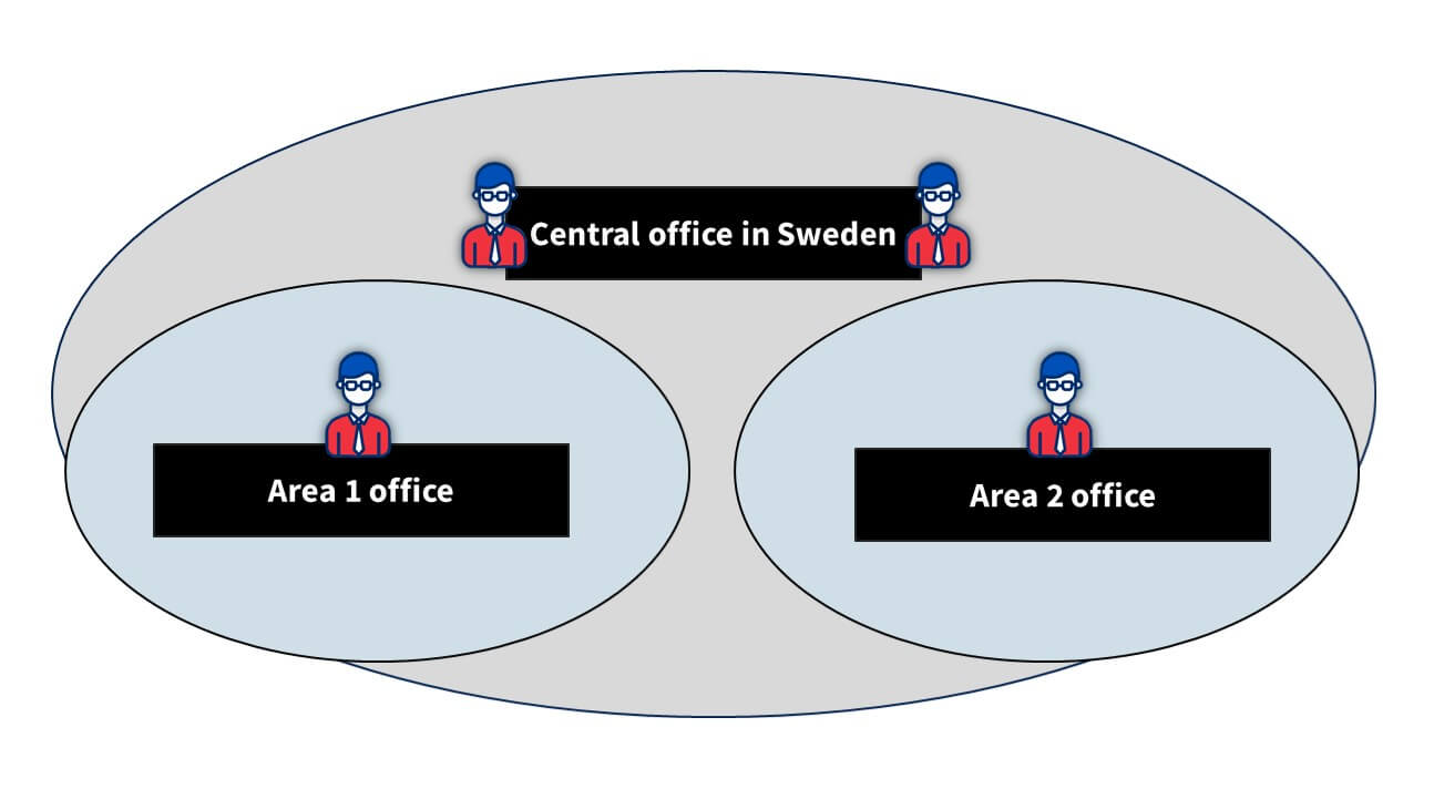
There are a few different options for us. As mentioned earlier, we work across the Nordics and Baltics. If we take the biggest of those – the Swedish office – they have more than 100 designers. But CES is also in Poland and Romania, so almost 200 all up which means if we create some smart tools, we want to make sure all designers can access them. We’re putting a lot of effort into making sure that everyone is using the same tools – don’t reinvent the wheel!
To share these tools and even some settings, we use Tekla’s firm folder capability. This is controlled by the main office in Sweden. However, in addition to that, we also utilize the project folder functionality, and that’s where we share the assets we create with all the Estonian, Polish, and Romanian colleagues.
We try to share as much information as possible in our company’s communications channels. This year, we started tackling the challenge of how we could check and verify that people are using these tools – but that’s another topic!
I assume your developments are all in English, given that you work directly with multiple countries. How do you manage that?
For us, it’s a transition period, because Consolis has historically acquired companies from many different countries, which means that in each one there are a lot of older tools, which are naturally in the local language. But now, all new developments are being done in English, which includes the UI, so that anyone from any location can easily benefit from the work of others. Having said that, of course, drawings are produced in the local language.
So you work with many different business units in various locations. What’s the difference between them?
Actually, I think the differences between them all are a lot smaller than people might believe. Of course, there are differences in the solutions made and so on, but the basics are always the same; you need to have a tool for adding lifting elements, you need to have a tool for adding connection items to elements, and so on. Naturally though, there are differences in different regions; our Finnish office might make really standard solutions; mainly for apartment buildings, and usually, the span of the hollow cores is very similar, and the wall elements are really simple. Whereas some of our Swedish business units do more tailored solutions as well.
You mentioned that, for example, different countries have different embeds and connections. How do you approach this? Do you use different firm folders? Project folders? Or different model templates?
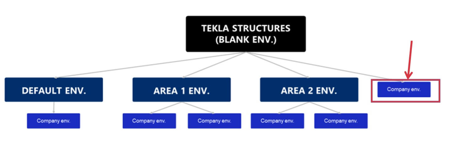
That’s actually something we are working hard on now in Consolis. We’re actually creating a common environment now for all Consolis companies. Historically each company has had its own Tekla environment, they have maintained them completely separately with their own firm folder and template settings, and so on.
Now, not everything can be standardised, of course; but the advantage will be that if you have more and more common tools, then you should share these common things. We have a separation of common tools which are the same for all business units, but then each unit has their own folders where they can store their localised templates and own content.
So you said the company is going to have a common environment. What are the benefits the company expects to realize from having it over the standard environment?
I think that it gives us the flexibility to use our own folder structure if there is a particular way you want to have it. But the main benefit really is to ensure that everyone in the company uses the same settings , and if it’s necessary to modify anything at a local level, you still have the flexibility to do so.
How big is CES Estonia? How many BIM managers are there?
Usually, in one business unit, there will be 1 Tekla specialist (or development engineer, however you would like to call it) who maintains the local part of the environment, and also provides support for the users if needed. But since we are a group, we also have someone at the central level to organize all the communications between the business units. So, we have development engineers at the group level, and even have engineers dedicated to developing tools at the group level.
Can you share any internal projects or tools you’re working on?
The best example right now is the project that has been running for a few years now, but we’re closer to making big steps in it. It’s our hollow core design tool. It’s an end-to-end process for designing hollow cores in Tekla structures.
It starts with getting the details of the project from our ERP system. From there, you then model your hollow cores, and what’s important here is that while the tool is part of Tekla’s floor layout tool, it’s also connected to our own databases so that the hollow core profile and info about the hollow core itself comes from our databases, to ensure the quality of the data in the model.
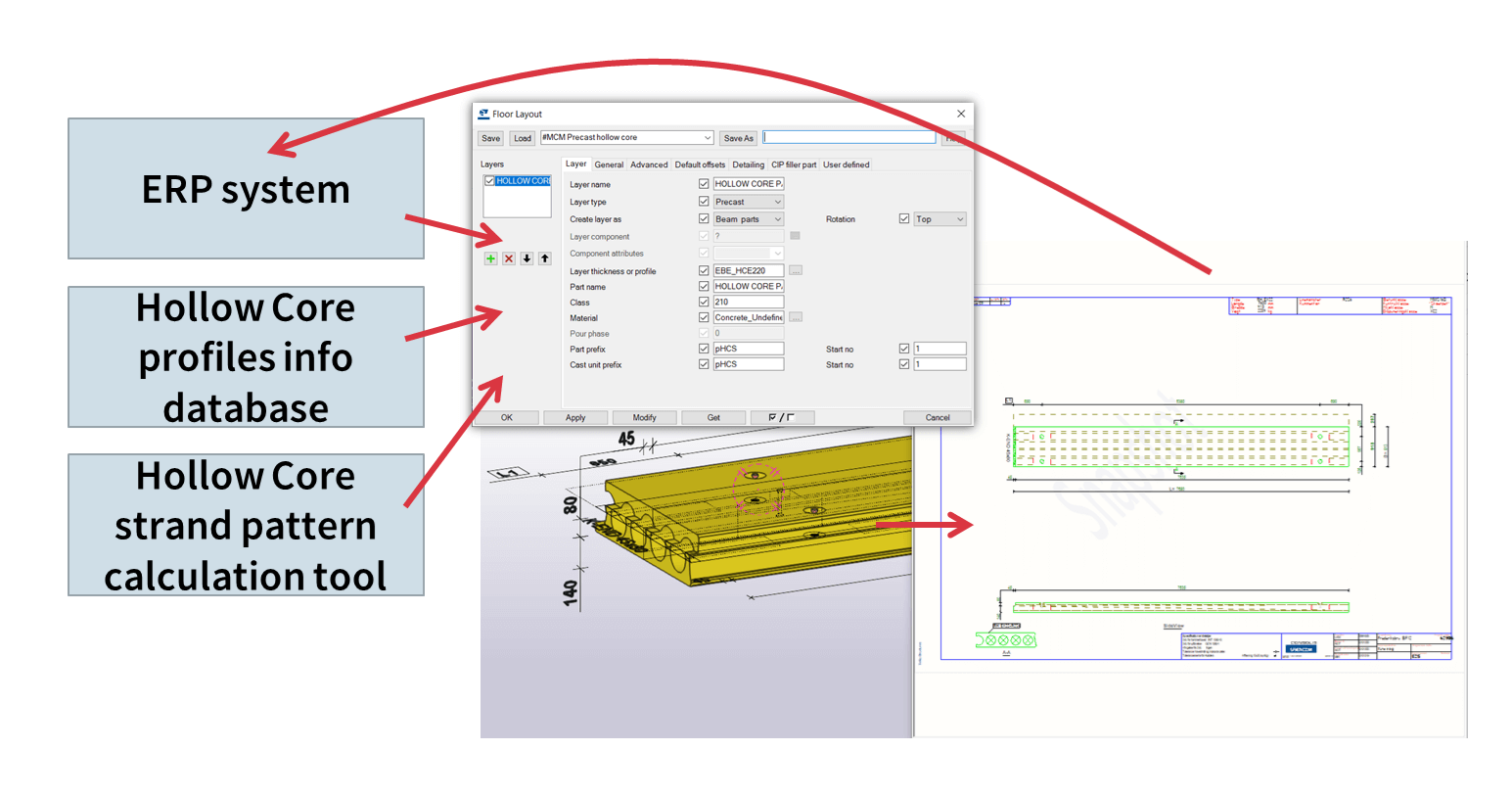
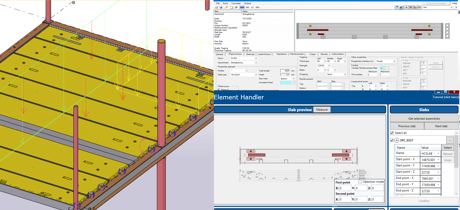
The tool is actually capable of calculating all of the hollow cores! So it calculates each one individually and applies the minimum strand pattern right there in the model. And the calculation is also done with an internally developed tool. And of course, the end result means you can generate the drawings automatically, and publish the information back to the ERP system for the factories to work with.
Can you give us an insight to the general workflow of your team in Estonia?
Well, that’s tricky to answer as there is generally no typical workflow! Of course, there is always the ideal workflow, but with each client comes input in a variety of ways, but ideally, we’ll get input in a usable format, even a Tekla model. But of course, the ideal solution is that we’d create the estimation (tender) project in Tekla, and it would be in a sufficient enough quality that if you need to work on it later to make it more detailed, it would actually serve as the basis for such work instead of having to start with a new project altogether.
This means we would use just one project from start to finish. I guess some of your listeners will know that sometimes the deadlines for tender projects are quite short – a few hours or maybe the next day, and you’ll create it really quickly and the result is not a very accurate model, meaning that later you will need to recreate it.
What would you say – of course, it depends on the project – but what can you say about how long it takes the company to make a tender model and take the quantities and based on these quantities, and make the offer?
From my own perspective, I think the reason tender models are sometimes not so accurate isn’t because you need to rush, but it’s more about the way you do it. So it could be that if you utilize the tool correctly, you use all of its functions, and all of its power, then creating the tender model in an accurate way wouldn’t be as time-consuming.
So you have your own ERP system and it’s connected with different systems. Can you explain how you use Tekla when you start modelling, and what kind of additional user-defined attributes do you use in the ERP, or some time scheduling statuses, costs etc?
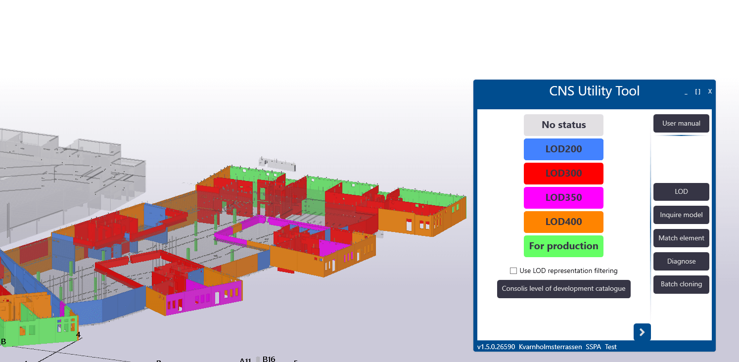
Of everything each unit uses, the one thing that all use is the design statuses. You can take any model in Consolis, and you can see what is the Level Of Development for each element. You can see it from the model, you can see it if you’re a project manager, if you’re a modeler, or if you’re doing estimations. Regarding the link to our ERP: at the moment we publish the element to our ERP, and there we have a lot of information about the elements.
From the basics, such as element geometry and so on, but also all the properties that we add as UDAs to the elements. But the interesting part is how we get the information back from the ERP. For example, what is the production status, is the element already produced, and so on.
What system do you use for communications and sharing information?
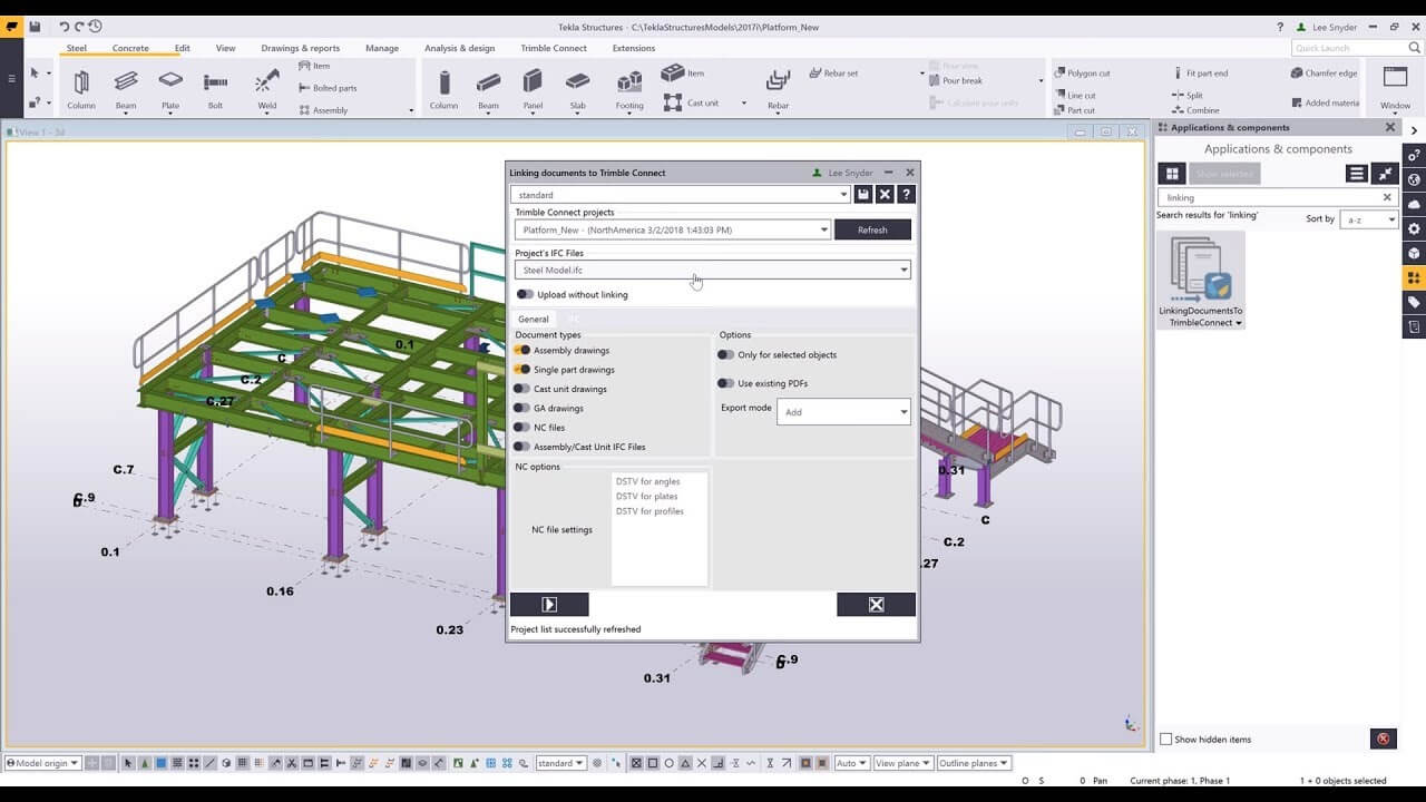
I’d like to answer as to what I would like it to be! It’s Trimble Connect, and we are not yet utilizing it to its maximum potential. But we know that in Trimble Connect, you can link drawings to the elements. For example, you can link the calculation files to the elements, so that would be the ideal case. But today, it is not implemented across the group right now.
What system do you use for calculations?
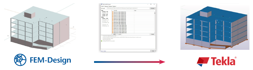
There are a few different systems, but one of them is StruSoft FEM Design, which is mainly used in Sweden, but also with our Romanian teams for global calculations. For calculating the elements, we have our own internal tools for calculating the hollow core elements and also wall elements.
Do you have any knowledge on how FEM Design connects with Tekla Structures? Do you do the calculations as a model?
I know that there is a link, but we haven’t used it. So currently there is still one model in Tekla and one analysis model.
What are your tips and tricks to improve Tekla structure model quality?
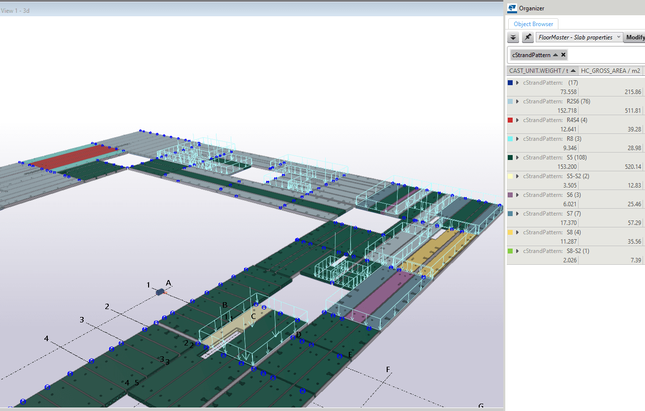
My most important tip would be to use Tekla Organizer. It’s really useful for looking at the model as a whole entity. So if you want to check some parameters for some specific elements, it’s really easy to do them in a list. For example, what are the different exposure classes? What are the concrete classes? And so on. You can use it to visualize that data in the model via different colors.
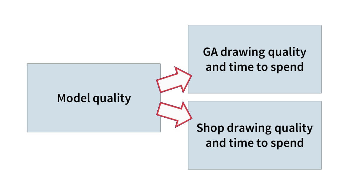
The second tip is around quality. The more effort you put into modeling and detailing in Tekla, and the more you use different tools and components you use in the modeling work, the less time you spend on drawings. A better model means fewer mistakes on drawings.
Do you think it’s possible to estimate how much time your engineers put into modeling and how much less goes into drawings?
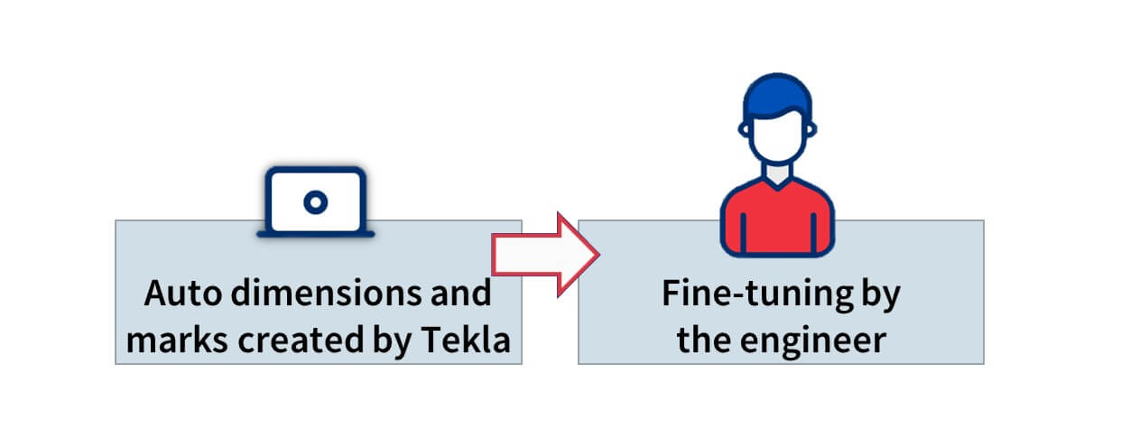
If we take, for example, walls, which are not quite as standard as hollow cores. Generating a drawing of a wall could take from 5 minutes to many hours. The best thing to do is use the auto dimension settings and marks settings and so on. For these kinds of elements, if you spend more than 15 minutes in a drawing, then that’s already too much. It shouldn’t be called creating a drawing, it should be called generating a drawing!
Any other tips on how to make Tekla more efficient or get results faster?
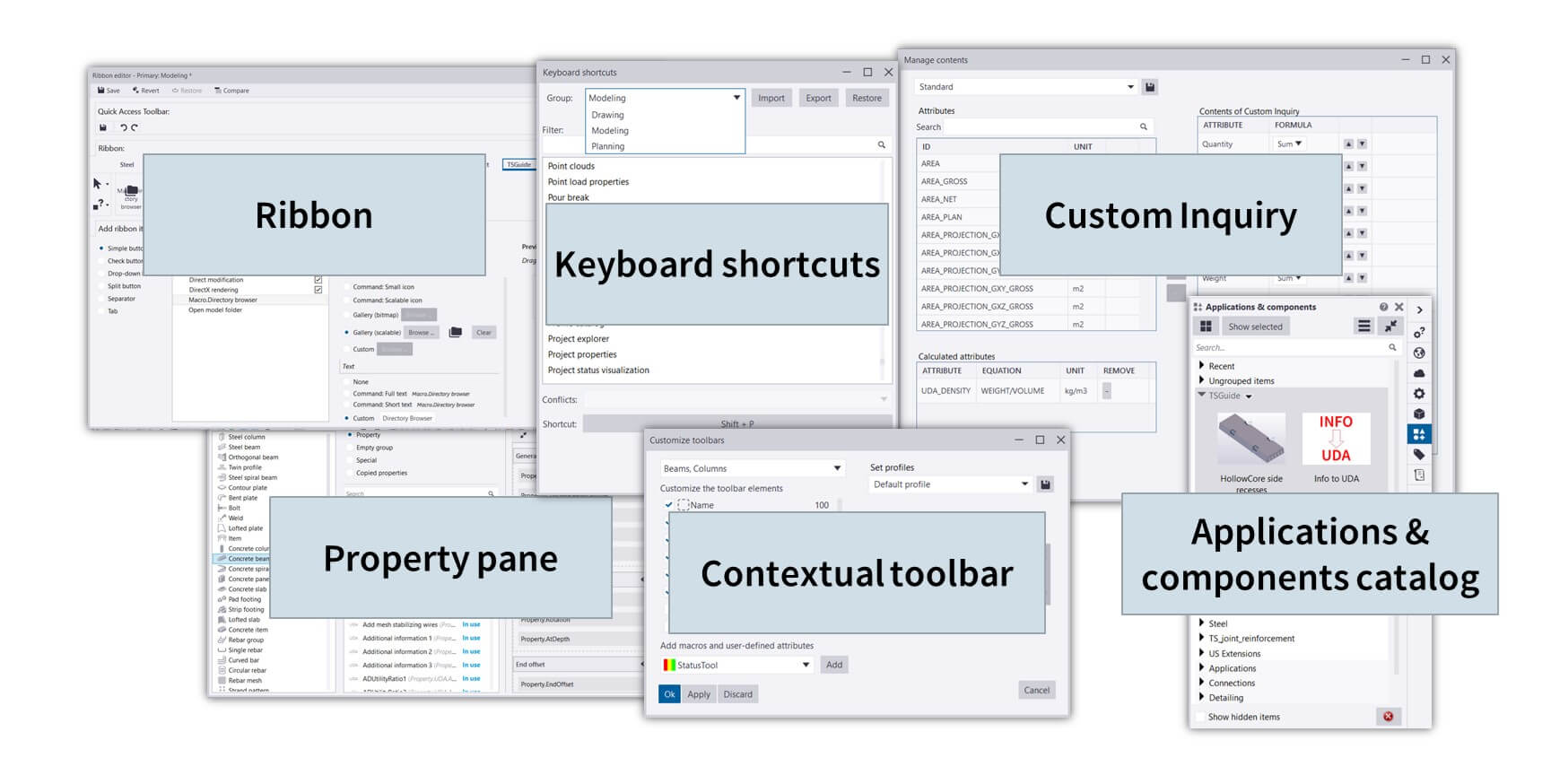
Yes. One thing that is clear is that different companies have different profiles. In Tekla, there are many different tools available in the toolbars and across the interface. For a lot of designers, you need to customize your Tekla workplace. So that what tools you have in the ribbon and what you have in the component catalog are structured in a way that you don’t need to constantly search for the ones you need most frequently. So it’s about taking the time to customize the Tekla UI to suit the work that your company does and the tools required to do so.
Can you share any project you were working on that was especially challenging, and how you overcame it?
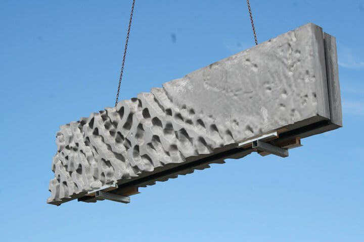
I have a lot of examples of these, especially with our Swedish company. Because we are working with precast, we all know that architects are very creative people and especially with our sandwich elements – or 3-layered elements – we have a lot of very interesting facade solutions that architects want to have. This can include quite complex designs, which are easy to manufacture at the factory, but how do we ensure accurate modeling of such components? In the newer Tekla versions, they have quite a lot of tools to help you make continuous step patterns or wave patterns that an architect may want to have as part of their facade design.
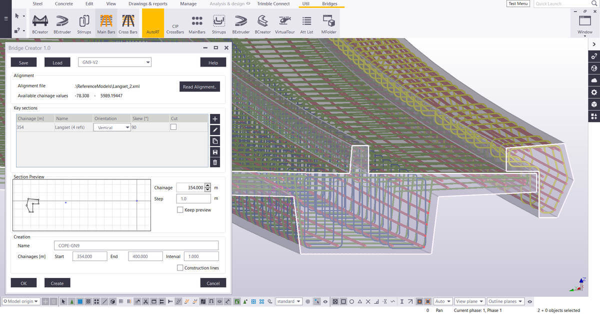
Another really interesting project we did last year – not me personally, but I was consulting a bit. We created a reinforcement model for a bridge, so it was really out of the scope of our usual work. Usually, we only work with precast, but it was a bridge in Estonia with a complex shape that was curved in different directions. It was quite a challenge to figure out the best way in Tekla structures to add rebars in these really complex curved elements. But we succeeded quite well and I must say, Tekla is quite flexible to help produce these solutions.
Why should companies make the switch from Autocad – which is free – to Tekla, which has a significant cost? What are the benefits of using Tekla over Autocad?
For me it would be quite tricky to explain it because I couldn’t even imagine working with Autocad again!
From the customer perspective, how drawings were produced and models were designed doesn’t really phase them. However, being able to have the as-built model is important if, for example, in 10 years’ time the customer wants to make changes to the building. You need to have the as-built model of course, and doing this with Autocad is really difficult to achieve.
But also more and more clients want to be involved in the process; it makes it easier to explain to the client what you’re doing and what you’re designing.
Have you measured things like the time taken to do a project, or the quality between the two?
When we switched to Tekla, we were not much more efficient in the beginning. That’s because in some ways, we were trying to use Tekla in the way we used to use Autocad.
So we were starting with the model, then created the drawing, and then did everything in the drawing manually. We added all the dimension lines manually, all of the marks, and a lot of modifications with hiding parts and showing parts, and so on.
But if you really use Tekla properly with all the automation, I’d find it hard to believe that I could create a model with Autocad more efficiently and with fewer mistakes than with Tekla. Especially with regards to quality, because in a 3D model it’s far easier to check for conflicts, especially as we get IFC models from other tools much more frequently now.
For example, ventilation design, piping, and so on. So if you get the up-to-date IFCs from the other designers weekly, then you can just easily check in the 3D world if you have conflicts with the other design parts. That is something that’s really hard to do in the 2D world of Autocad.
What are the company’s plans for Tekla internally for its development? Where are you planning to take it?
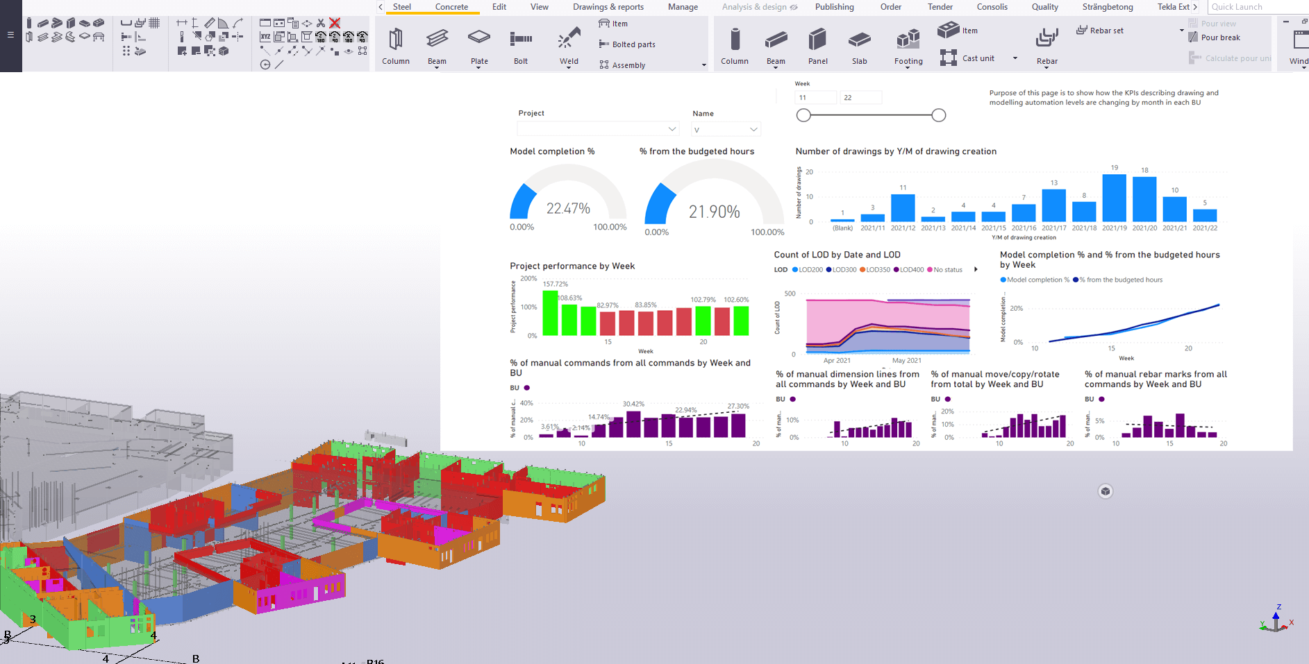
We’ve been thinking about this quite a lot. We are doing a lot of different developments, we have a huge number of designers, in different countries who are working in different ways, but it seems to us more and more that we haven’t had the data on where is the time going in the models? How can we use it more efficiently, how can we tell if the designers are using the tools that we provide them with?
So there is one thing we’ve started where we can gather some information about the usage of Tekla, and through that, we’ll be able to see through all of our designers how many custom components they were using during that period. And also if we create some automation settings for drawings, we can check and see if these settings are being used.
And it’s not just about tracking the tools we have created; it’s also about understanding which tools we are NOT using. So that we can compare between different business units and companies, that maybe there are some very productive practices one company is using and others are not (usually it’s because they are just not aware that it’s there), so then we can spread that knowledge and as such, improve efficiency and accuracy and so on.
Really use the information to make decisions, not based on feelings.
The same goes for following the information about projects and Tekla models. Create reports automatically, for example, daily, and use other tools for analyzing the data. For example, you can have live up-to-date dashboards for different models, where you can use data about the history for making project future predictions.
Generally in the BIM world, or globally, how do you see things are going?
A lot of things will happen! But there are definitely a few standing points to look at that from; in the world we’re in right now, we all know that we need more and more information for different reasons and purposes.
If I were to start with the environmental impact that the industry is having on the world itself, then more and more customers – especially in the Nordic countries, and others – really want to get information about their buildings. For example, the carbon footprint of the building. And, if you don’t have a proper model with accurate, thorough information about different points such as where is the concrete coming from, where is the steel coming from, what embeds are you using in your elements – if you don’t have that information, then it’s impossible to calculate any kind of carbon footprint.
So that’s a major thing in BIM; that for each material or element, you put in the model – there is some kind of connection to your IDE or database – what really is the material being used?
One example is even what factory the component is manufactured in. For us, we produce pre-cast elements, but for the customer, there’s a big difference if we produce it in a factory 2000km away from the site versus at a factory 200km from the site, owing to the amount of carbon emitted in the transportation. So realistically, if I were to go into the ERP and change the factory the element is going to be produced in, the client then can see an tangible difference in the carbon footprint of the construction of the building.
AUTHOR

Tekla Structures grandmaster and TSGuide OÜ founder.
FIND THIS USEFUL? SHARE IT!
[Sassy_Social_Share_Pro]