Tekla Podcast #4 – aluminium facade/curtain wall with Tekla (Jānis and Artis from UPB)
9 min read + 46 min interview
Tekla Podcast episode #4 is the second session with Artis and Jānis from UPB, a Latvian company that has been around for about 30 years. They specialize in integrated solutions for complex constructions, and with almost 200 engineers on the books it’s no wonder they have been a continued success in the industry.
Just in case you didn’t check out podcast #3, Artis Aizstrauts is the head of R&D of UPB; an accomplished researcher with over 20 publications to his name, and Jānis Goldmanis, is an R&D Project Manager with more than 9 years’ of Tekla Structures & engineering experience.
Watch the whole interview video here:
or listen it in audio format here:

Don’t have time to watch the whole pod? Skim the questions and answers summary in a written format below! 👇
Why did UPB go into this segment of doing aluminium facades, and especially with Tekla Structures?
Jānis: We had been doing 2D drawings in Autocad as recently as 3 years ago, and the projects were getting larger and more complex. In the facade sector, there are so-called “System softwares”, where each manufacturer of that profile system has their own system software, where you simply input the width and the height of your element. And the software will then output everything that is necessary.
But these larger projects normally require custom solutions – systems from the catalog are not good enough. Because of this, if we were not using the system software, then instead we were using Autocad, where everything needed to be done manually.
As mentioned, with the projects getting larger and larger, we knew we had to make a change. We evaluated several different systems including Revit, Tekla, Solidworks, and more.
Each had their advantages and disadvantages, naturally. But in the end we went with Tekla – partly because we were more familiar with it – but also because of how customisable it is.
There are two main benefits that helped sway our decision: first of all, Tekla is capable of handling very large models, and additionally, those models themselves could be very detailed.
It has to be said that perhaps out of the box Tekla wasn’t the best at detailing for facades. For example, if you look at Solidworks, it’s much more suited to fabrication, but it is only capable of handling one single element. Whereas Tekla was capable of holding the entire model.
We also evaluated the customization options available via API, and we decided that we would be able to customize it to the needs of our facade division.
API developments – why did you go down that route?
Artis: Firstly, in Tekla you can model whatever you want – OK, fine. But the big question when it comes to facades is how. They are so much more complex than concrete and steel. There were a lot of questions that needed answering. So, we created an R&D team specifically to help implement Tekla in the facade unit.
The team was comprised of Tekla experts from our Heavy (steel and concrete) division, and facade experts. The facade experts know what needs to be done to produce the final product. The Tekla experts know how much is possible to be done in Tekla.
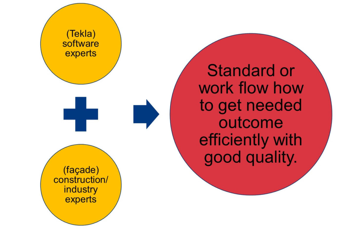
Based on the knowledge of these two halves of the team, we developed our own standard for modeling facades in Tekla. Once we had the standard (documentation), we developed tools to do it all faster, and then we were able to start switching to Tekla in the facade unit. It was a very sensible approach to implementation, and doubtless saved us a lot of time.
Using these tools, how much faster does the work take now compared to when Tekla was first used? What are the struggle points that they still have?
Jānis: It can be hard to put it into exact numbers! What we do know is that in the beginning, things were naturally a bit slow as we all got used to the new methods. But, after 3 or 4 projects, we already knew that we were working at a similar speed compared to when we were using Autocad. But the difference was day and night with what we were actually doing.
The time saving and benefits (for example, the time it takes to generate quantity take-offs) of working in a new way don’t increase linearly with the increase in the size of a project. It increases exponentially.
With Autocad, we were limited to projects that consisted of something like 500 elements. That is, that’s as big as the project could be, and still be somewhat manageable.
With Tekla, we have done projects with 3000 elements. It’s still very manageable within one very large model. Also, it isn’t just about the speed; the main point is that we have enabled this process that allows us to handle a project so large. With the same team, we can now manage projects 6 times larger than before. With Autocad, it would be impossible.
Now that we are more experienced and have completed a lot of projects, and we’re learning even more advanced methods and developing new tools, the speed also increases. I’d say that now, even the speed is faster than it was before with Autocad. And even then, that isn’t the most important benefit.
The biggest benefits realized have been the scale of projects that we can undertake, and the amount of useful information that can be created to go along with it to pass down the line-manufacturing, logistic, assembly.
Can you give us some examples of using information like elements size, weight, and location to plan installations and transportation?
Jānis: When the engineers produce a model, it tends to be a rough sketch. However, this includes information such as the overall size of the elements, and their locations.
This data is immediately accessible to the assembly team as a 3D model, and straight away they can start planning the installation sequence together with the project manager.
That information immediately arrives at the factory, and in turn they can plan the manufacturing processes. Since they already know the rough sizes of the elements, what kind of profiles, what kind of bars are needed, and so on.
For facades, the material orders are very important, since some of them can take as long as 3 months to arrive. So, having that information as soon as possible is a huge plus.
Also unique to facades is that the materials required are generally very expensive; much more so, relatively speaking, than precast concrete or steel. We need to be particularly efficient with materials ordering for manufacturing, and from the 3D models we can very quickly extract data about what is needed.
For example, say there are 20 km of aluminium profile in the facade, we can immediately optimize how many bars, and in what length, that need to be ordered.
Add to this, that at any moment, the assembly sequence can change, for a number of reasons. For us, it’s now easy to deal with, since we get the new installation sequences from the assembly team. Then we can re-optimize the materials, and change the manufacturing order, so that everything is done efficiently.
“We calculated that quantity take-offs using DWG took around ~17% of an engineer’s time; in Tekla, it’s almost immediate.”
Can you show us an example of how you are creating aluminium facade elements in Tekla?
Editor’s note: This part of the interview is really best enjoyed by watching the video. Jānis goes on to demonstrate a host of tools that they have developed in Tekla for all sorts of amazing efficiency gains. Check it out!
How was it in the beginning to start doing these aluminium facade elements manually?
Jānis: There was a lot of experimentation in order to find the correct approach! As mentioned earlier, we have developed our standards, but in order to develop them, we had to go through different iterations of models, and different projects where we tried different approaches.
For example, with the very first model, all of us were Tekla experts. And we decided to go with Tekla’s custom components. We created some very complex custom components. But, that didn’t work, and we had to finish the project using manual methods!
For the next project, we decided to replace these components with plugins. And now we know that to be the best option.
When would you recommend using custom components, and at which point would you change to OpenAPI?
Jānis: So, connections should definitely be custom components, since they’re unique from project to project, and it’s almost impossible to make a comprehensive plugin that solves everything. The connection creator I showed in the demo which made these fittings – well, that is its sole purpose.
If you need to do some custom bolt connections with the inside connectors, the idea is that you make it as a custom component, and then you import it within this tool. You should definitely think about doing plugins if you have creation criteria.
In some places you need to create something, and in others, you don’t. For example, this unitized frame; normally with unitized elements, they look the same – but in fact, they have some small differences.
For example, every second element doesn’t contain the middle vertical beam. This needs to be produced either by two custom components, or a plugin that can handle all of the cases; it shouldn’t be one complex component.
Also, a very big no-no is creating complex parametric custom components within parametric custom components! It will collapse very quickly; your project will stop working as expected. Having a simple “Array” component working inside your custom component is ok.
How much time and effort have you put into these custom components and these API plugin developments?
Artis: It’s more or less 4000 man-hours over the course of around 3 years. If we remove the huge experience in Tekla or facades, well you can’t do that only with developers. The developing part is the easiest; what took the largest amount of time was the “how” question.
As I mentioned earlier about the standards and methods of creating the model and its structure – this is where a lot of time was taken. Determine and finalize things like what is the assembly, what is the component, what is the plugin, and so on.
As Jānis mentioned, at the beginning you may think “Yeah, that should work, because it worked with steel or concrete”. But as he said before, one element in a precast wall has how many details? Say, 20? But a facade element will easily come in at ten times that amount.
Trial and error was the only way to go, and that’s what clocked up the most hours out of that ~4000.
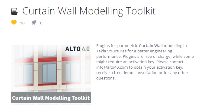
Where can people get access to these tools?
Artis: Yes, we have published them in the warehouse. You can get them from HERE. There is also a lot of supporting documentation and videos to go along with them.
Who would get the benefits from these tools, what kind of companies or customers should use these?
Jānis: Companies that are switching from 2D DWG (Autocad or any other similar software) to Tekla would get the most benefit from these tools. They won’t have to figure out all of these things themselves. They can start benefitting from our experience in a reasonable amount of time.
The alternative to that is that you need very experienced users who are capable of quickly creating complex custom components to replicate what we are doing with our plugins. What the tools achieve is to lower the bar of entry – the qualifications and experience required of the users.
Since, for precast and steel, I’d say the bar is much lower for what qualifications/experience an engineer would need in order to generate an optimal workflow. For facades, it’s much higher, and the plugins really help with this.
Your final recommendations: How to reduce project mistakes and raise efficiency?
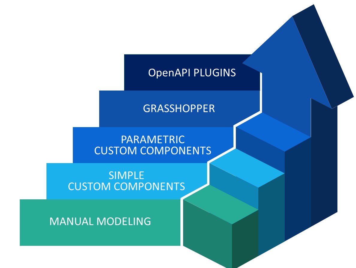
Jānis: Mistakes can be eliminated if you don’t try to do something more complex when you haven’t already learned how to do it with simpler methods. First of all, you should really learn Tekla’s basic functionality; so, do something manually.
Next, learn how to use automation in Tekla; how to make simple custom components, such as simple drawing templates.
Once you’ve mastered that, move up to parametric custom components. With more time and experience, you should then move on to considering introducing Grasshopper.
Don’t create one super custom component that does everything, because when something goes wrong, it will be very difficult find out where the problem is if things aren’t working as expected.
Instead, separate everything into small, modular steps; separate small custom components that combine together to achieve what is necessary for you.
Finally, never stop improving yourself. The more you learn, the more you understand how much you don’t know yet!
Go check out our last podcast episode also with Janis and Artis here.
AUTHOR

Tekla Structures grandmaster and TSGuide OÜ founder.
FIND THIS USEFUL? SHARE IT!
[Sassy_Social_Share_Pro]